While many layout rules can be applied equally between analog and digital layouts, the following are the most important rules when creating analog circuits:
Component placement should be tight
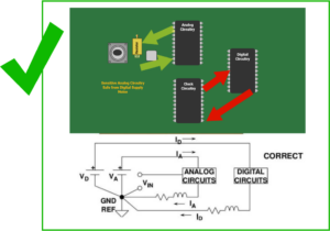
Analog signals must be short and direct, and the best way to achieve this is to start with good placement of analog components in tight locations. This will not only simplify the direct routing of the alignments, but will also help keep the analog and digital circuits separate. Also, remember to place noisy analog sections toward the center of the board rather than along the perimeter. This will allow grounding layers and other circuitry on the board to help suppress certain noises.
Provides isolation between analog and digital circuits
Because both analog and digital components can have noise effects on each other, it is best practice to place the board in such a way that they are as separate as possible. With this separation of parts, you need to avoid routing high-speed digital alignments through the analog circuit area. Noise from digital signals can affect analog circuits.
Signals must be short
At higher frequencies, impedance mismatches can cause analog signal reflections. These reflections can create electromagnetic interference (EMI) in other components on the board. The best way to prevent this is to route the analog signals as short and direct as possible. Another good tip is to keep the alignment on one layer, which will help reduce the number of vias and lower the inductance of the circuit.
Using a dedicated mock ground
The digital grounding layer on the board will be busy with all the digital signal return paths and will filter the power spikes generated by fast switching high-speed digital components. All of this activity creates a lot of interference with your analog circuitry, so the best practice is to create a separate grounding layer. The digital and analog ground layers can be connected at a single point, but it is important to keep them isolated.
Ensure a clear path back to the analog signal is provided
Not only do you want to make sure that the analog signal routing is short and direct, but the signal return path on the analog grounding layer must be as clear as possible. Designers often block the direct return path of signals from flowing through vias, planar splits, or cutouts and gaps. This blockage forces the return signal to wander around the grounding layer trying to find the shortest path back to its source, creating unwanted noise along the way.
These are five key points to keep in mind when laying out analog circuits. Remember, even with these recommendations, you still need to follow Design for Manufacturing (DFM) rules to ensure that the board can be assembled correctly.

