PCB design is a must for electronic engineers, and it’s no easy task to design a perfect PCB. A superb PCB board must not only ensure component selection, but also excellent signal conduction performance. This article will give a brief introduction to the PCB high speed signal circuit principle in the alignment method expertise, expecting to be of some help to the big guys in their work.
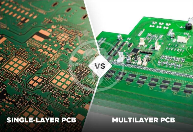
The vast majority of technical engineers choose to apply multi-layer circuit boards for high speed signal board wiring throughout the entire process of PCB specific design solutions. These multi-layer circuit boards are an integral part of the composition, all of which are a reasonable way to assist hardware engineers in reducing the impact of power supply circuits. The newest addition to the lineup is the newest addition to the lineup, which is the newest addition to the lineup.
In addition to the above-mentioned types of multi-layer circuit boards to improve the reliability of PCB signal transmission, there is also a portion of authoritative information showing that the same raw material four-layer board than double-sided circuit board noise is 20dB lower. the lower the wire bend the higher, the best choice is to use all parallel alignment, must turn the point of words can use 45 degrees curve or arc turning point, can reduce the high-speed signal open to the outside of the emission point The best choice is to choose a fully parallel alignment.
The lower the wire virtual beam turnover between the pins of each high-speed power circuit component, the higher, meaning the lower and higher the pads commonly used for the full range of component coupling. In general, a pad can create a contact resistance of about 0.5pF, which will cause the delay of the power supply circuit to continue to rise. In addition, high-speed power circuit alignment to pay attention to the signal lines close to the parallel side of the wiring imported by the “cross-type impact”, if you can not prevent the parallel side all over, can be laid out in the parallel side of the back of the signal line large-scale “ground” to reduce the impact. In the adjacent 2 layers, the wiring is oriented as vertically as possible to each other.

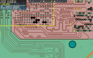
The very critical signal lines should be partially surrounded by the module implementation ground wire, which can be in addition to the signal wiring such as clock signals, high-speed analog signals, etc. that are not susceptible to the impact of the maintenance ground wire in the outer field, i.e. the maintenance signal wire is sandwiched right in the middle. All kinds of signal wiring is not allowed to produce loops, the same grounding line is not allowed to produce an electric flow loop. And if it causes a loop alignment power circuit will cause a pretty big impact in the system software. The choice of ground wire around the signal line alignment, can reasonably prevent the generation of loops when the alignment. One or more high frequency decoupling capacitors should be set around each IC chip block.
Auto Sync with Cloud
No manual interaction required to synchronize with cloud services.
Differential signals are specified on the same layer and wired as close to the parallel side as possible, and differential signal lines are not allowed to be inserted in the middle of all signals, and should be equal in length and spacing. The wiring minimizes high speed signal hair or tree stump generation. High-frequency signal lines on the surface is very easy to cause a lot of electromagnetic radiation, high-frequency signal lines in the middle of the switching power supply and grounding lines, according to the switching power supply and the bottom of the digestion and absorption of radio waves, the source of radiation caused will be reduced by many.
The most sensitive signals in a microcontroller (MCU)-dominated system are timing, reset, and interrupt signals. Oscillators are especially sensitive when switched. These circuits should not be parallel to the high current alignments to avoid signal interference and misclassification. The oscillator or ceramic resonant clock is an RF circuit that must be effectively laid out as the closest distance with the shortest alignment to reduce its sensitivity. The oscillator circuit should be laid out as close as possible to the microcontroller in a symmetrical location so that the alignment distance is the shortest. The ground of the oscillator circuit should be connected to the ground pin where the component may use the shortest path, and the power and ground pins should be connected directly to the power section of the PCB.
