

Bookbinder rigid-flex PCBs are specialized multilayer structures designed for short, tight bend regions.
Instead of making every flex layer the same length, this approach staggers the layers so the outer flex layers extend farther than the inner ones. That geometry better matches the way a multilayer circuit bends, helping reduce wrinkling, buckling, and localized mechanical stress.
This matters most in 180-degree bend applications and other compact designs where bend reliability is critical. In those cases, a bookbinder rigid-flex PCB can provide more uniform layer spacing and more stable mechanical performance than a conventional equal-length flex design.
Quick Answer
A bookbinder structure is a rigid-flex design approach in which the flex layers in the bend area are made progressively longer from the inner layer to the outer layer.
This helps the layers follow more natural bend paths, maintain more uniform spacing, reduce wrinkling, and improve interconnect reliability in short multilayer bend regions. It is most useful in high-reliability designs, but it is usually not ideal for cost-driven, high-volume consumer products because it requires special tooling and lowers manufacturing efficiency.
Why Short Bend Areas Are Harder Than They Look
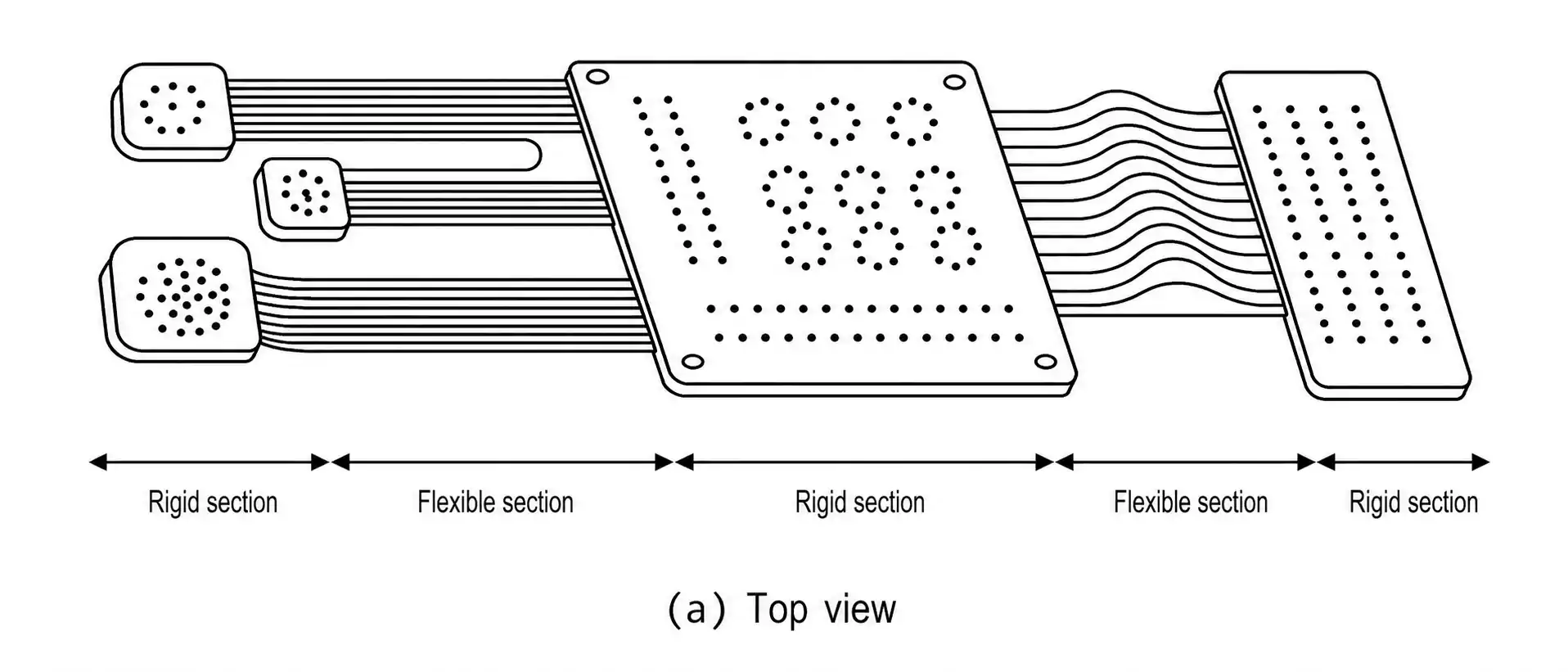
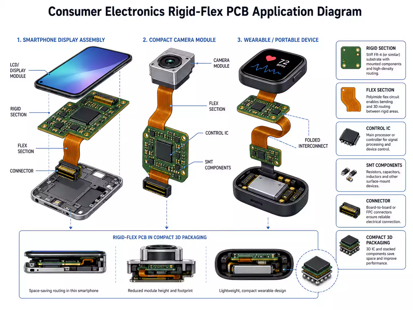
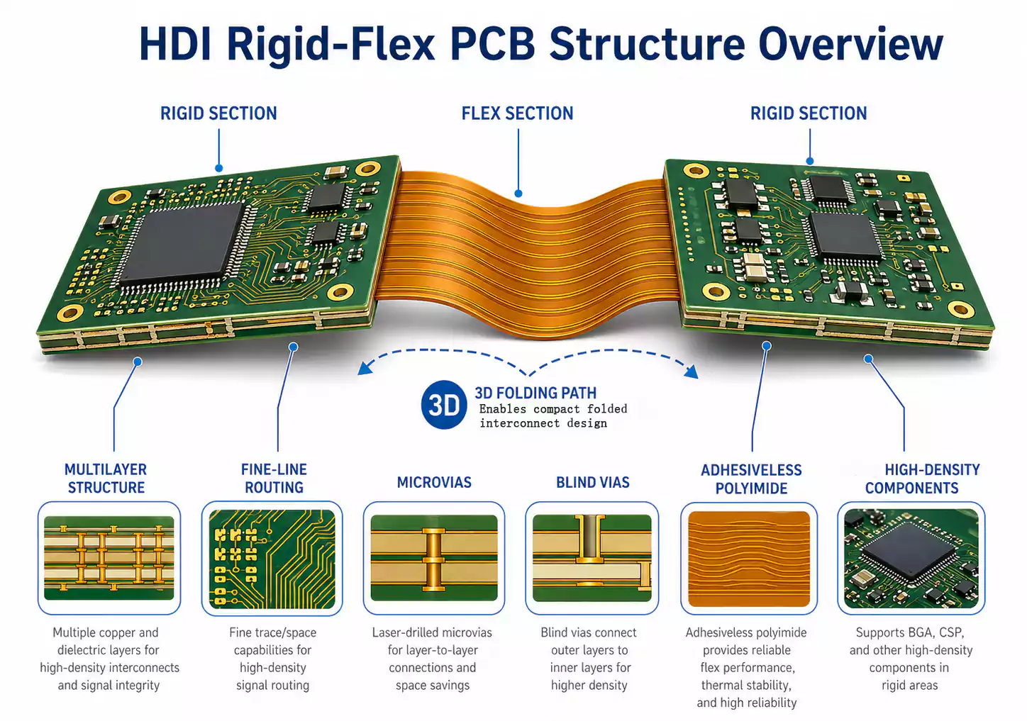
A rigid-flex PCB is not just a rigid board with a flex tail attached. It is an integrated structure made up of:
- rigid sections for component support
- flexible sections for bending and folding
- transition zones that must survive both manufacturing and use
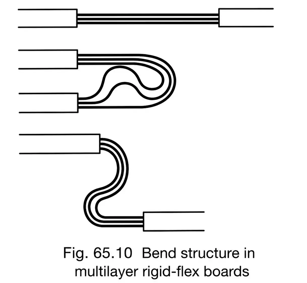
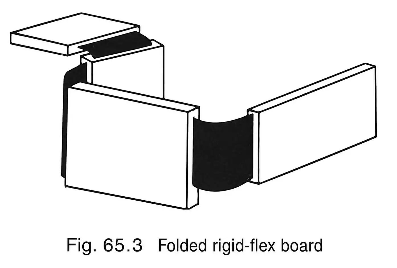
Rigid-flex boards can be designed in several structural forms, including folded, flying-tail, and bookbinder types. Those formats are not just visual differences. They reflect different mechanical and reliability strategies.
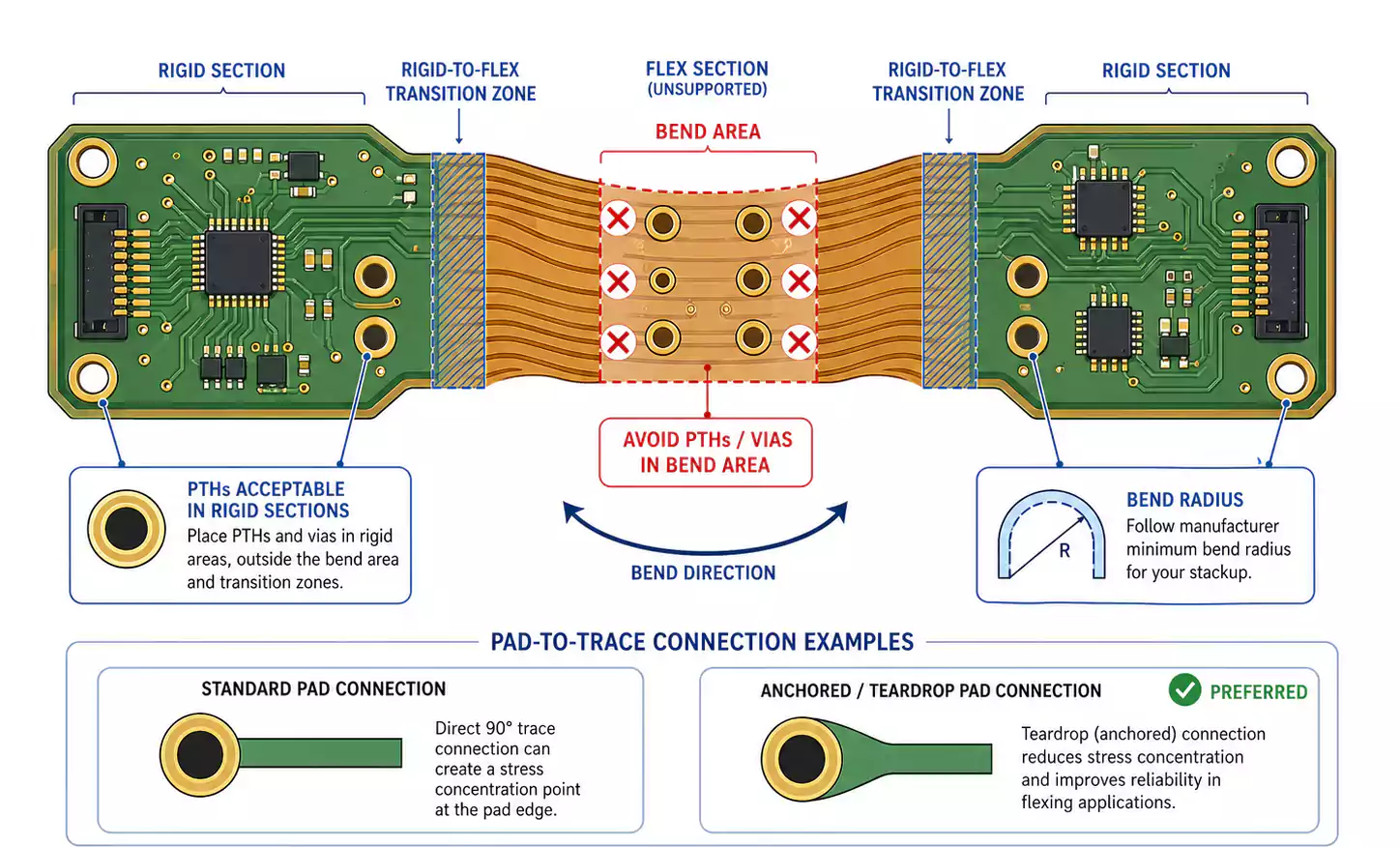
In a multilayer flex area, each layer follows a different bending path:
- outer layers travel a longer arc
- inner layers travel a shorter arc
If all flex layers are designed to the same length, the geometry does not match what actually happens during bending. That mismatch can lead to:
- uneven spacing between layers
- local wrinkling
- unbalanced strain
- lower long-term interconnect reliability
This problem becomes more severe when the bend area is short.
What Is a Bookbinder Structure?
A bookbinder structure is a multilayer rigid-flex bend design in which the flex layers increase in length progressively from the inside layer to the outside layer.
The name comes from the way the layers resemble the pages of a book. When a book opens, the inner pages effectively travel a shorter path, while the outer pages travel a longer one. A bookbinder rigid-flex layout follows the same logic.
Instead of forcing every layer to bend as if it were on the same radius, the design gives each layer a more appropriate length for its actual position in the stack.

What that improves
- more uniform layer-to-layer spacing
- less wrinkling in the bend area
- better mechanical stability during bending
- improved interconnect reliability in short flex regions
Why Equal-Length Flex Layers Often Fail in Short Bends
Equal-length flex layers may look simpler on paper, but they do not behave well in every structure.
When a multilayer bend region is short, the layers have little room to accommodate differences in bending paths. That is why equal-length designs often create a mechanical mismatch. In practice, this can manifest as crowding, distortion, or non-uniform stress throughout the flex stack.
In simple terms
| All flex layers same length | Layers are forced into mismatched bend paths | Higher risk of wrinkling and uneven strain |
| Bookbinder structure | Layer lengths better match actual bend geometry | More uniform spacing and better reliability |
The core idea is simple: short bend zones need more intentional geometry control.
Bookbinder Structure vs. Free-Flex Layered Structure
These two ideas are related but not the same.
A free-flex layered structure improves bendability by leaving flex layers unbonded, allowing them to move independently. In high-reliability rigid-flex designs, which can significantly improve bending performance. In some extreme cases, this kind of approach has even supported very high layer counts.
A bookbinder structure goes further by adjusting not only whether layers can move, but also whether each layer has the right length for the bend.
The difference at a glance
| Free-flex layered structure | Increase layer freedom by avoiding bonding between flex layers | Longer bend areas, thin materials, high-flexibility designs |
| Bookbinder structure | Stagger layer lengths to match bend geometry | Short bend areas, multilayer designs, high-reliability applications |
If the bend region is long enough and the film and copper are thin enough, a free-flex layered structure may already be sufficient. But when the bend area is short, a bookbinder structure is often the better solution.
When a Bookbinder Structure Makes Sense
A bookbinder structure is worth serious consideration when several of these conditions apply:
- The design is a multilayer rigid-flex
- The flex section is short.
- The bend area is mechanically critical.
- The product requires high interconnect reliability.
- The project can tolerate more fabrication complexity.
That is why this approach aligns much more naturally with high-reliability design than with cost-driven mass production.
Why It Shows Up in High-Reliability Designs
Rigid-flex technology was developed early in applications where space was limited and reliable interconnection was essential. In those environments, the goal was not always ultra-fine routing or the smallest possible microvias. The higher priority was stable bending behavior, mechanical durability, and long-term reliability.
A bookbinder structure fits well with that design philosophy because it directly addresses one of the most failure-prone regions of a multilayer rigid-flex PCB: the short bend.
It is not a decorative feature. It is a mechanical reliability strategy.
Why It Usually Does Not Fit Cost-Driven Consumer Products
The tradeoff is clear: a bookbinder structure requires special tooling and equipment, and production efficiency is relatively low. That makes it hard to justify in high-volume consumer electronics, where cost, throughput, and manufacturability are major priorities.
Consumer products usually aim for a different balance, including:
- high routing density
- thin overall construction
- low material cost
- efficient mass production
- better panel utilization
That is why consumer-grade rigid-flex design often relies on thinner materials, controlled layer counts, and manufacturing approaches optimized for cost and throughput rather than maximum bend-zone reliability.
A Bookbinder Structure Does Not Replace Good Rigid-Flex Design
Even when a bookbinder structure is the right choice, it is still only one part of the design strategy.
Rigid-flex performance also depends on:
- material thermal stability
- dimensional stability during processing
- lamination quality
- moisture control
- drilling and desmear process control
- through-hole reliability
For example, high-reliability applications often favor thicker polyimide films, while adhesiveless copper-clad materials can offer better heat resistance, lower thermal expansion, and reduced finished thickness.
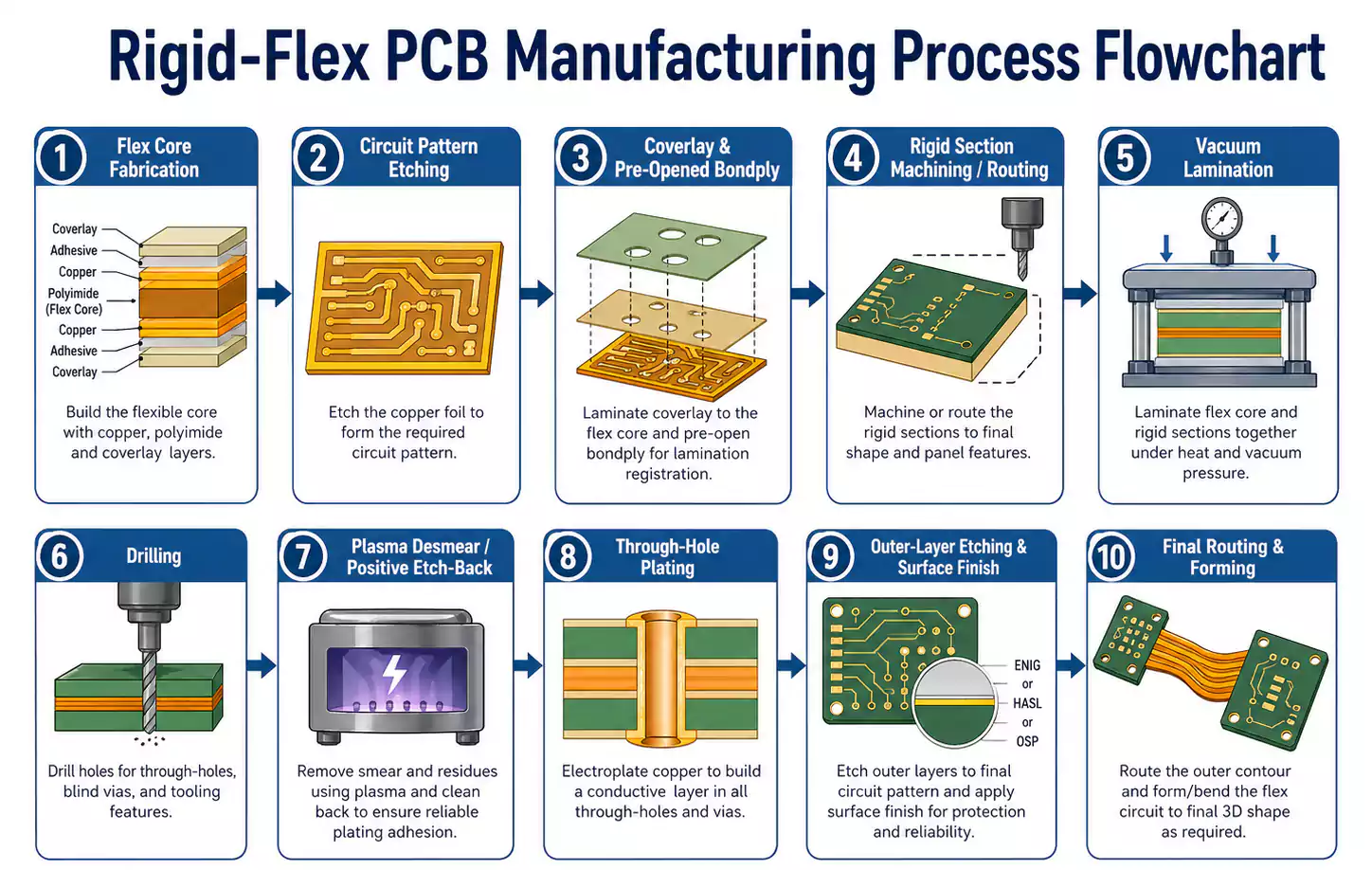
The fabrication process is also demanding. Typical rigid-flex manufacturing may include:
- flex circuit patterning
- coverlay application
- bondply windowing
- rigid outer-layer pre-machining
- controlled-depth routing or cavity formation in the flex region
- vacuum lamination
- baking
- drilling
- desmear
- plating
- final profiling
Through-hole reliability matters as well. In high-reliability builds, pre-drill baking is important, and plasma desmear is often preferred because potassium permanganate can cause swelling in acrylic adhesive systems. Positive etchback can also improve the reliability of plated-hole connections.
The main point is this: a bookbinder structure improves bend-zone geometry, but it does not eliminate the need for solid materials and process control.
When You Should Seriously Consider It
Use this checklist as a quick filter.
A bookbinder structure is a strong candidate if:
- You have a short multilayer bend region.
- Bend reliability is a major design concern.
- The board will be used in a high-reliability environment.
- The manufacturer can support the added complexity.
- Performance matters more than production speed.
It may be unnecessary if:
- The flex region is relatively long.
- The layer count is moderate.
- The materials are thin enough to bend easily.
- A conventional free-flex layered structure already meets the requirement.
FAQ
What is a bookbinder structure in a rigid-flex PCB?
It is a bend-zone design method in which flex layers increase progressively in length from the inside to the outside. This helps the layers bend more naturally in short multilayer flex regions.
How is it different from a free-flex layered structure?
A free-flex layered structure improves flexibility by leaving the layers unbonded. A bookbinder structure focuses on giving each layer a more appropriate length for the bend.
When should a designer consider using it?
It makes the most sense in multilayer rigid-flex designs with short bend areas and high reliability requirements.
Why is it uncommon in consumer electronics?
Because it requires special tooling and reduces production efficiency, it is less suitable for highly cost-sensitive, high-volume products.
Final Takeaway
A bookbinder structure is a targeted solution for a short multilayer bend area.
When equal-length flex layers create uneven strain, wrinkling, or spacing issues, a bookbinder layout provides a more controlled bend geometry and better interconnect reliability. In the right design, it does not add complexity for its own sake. It is the more reliable engineering choice.
At FastTurnPCB, this kind of decision is best evaluated within the full rigid-flex design context, including stackup, materials, manufacturability, and reliability requirements.
