

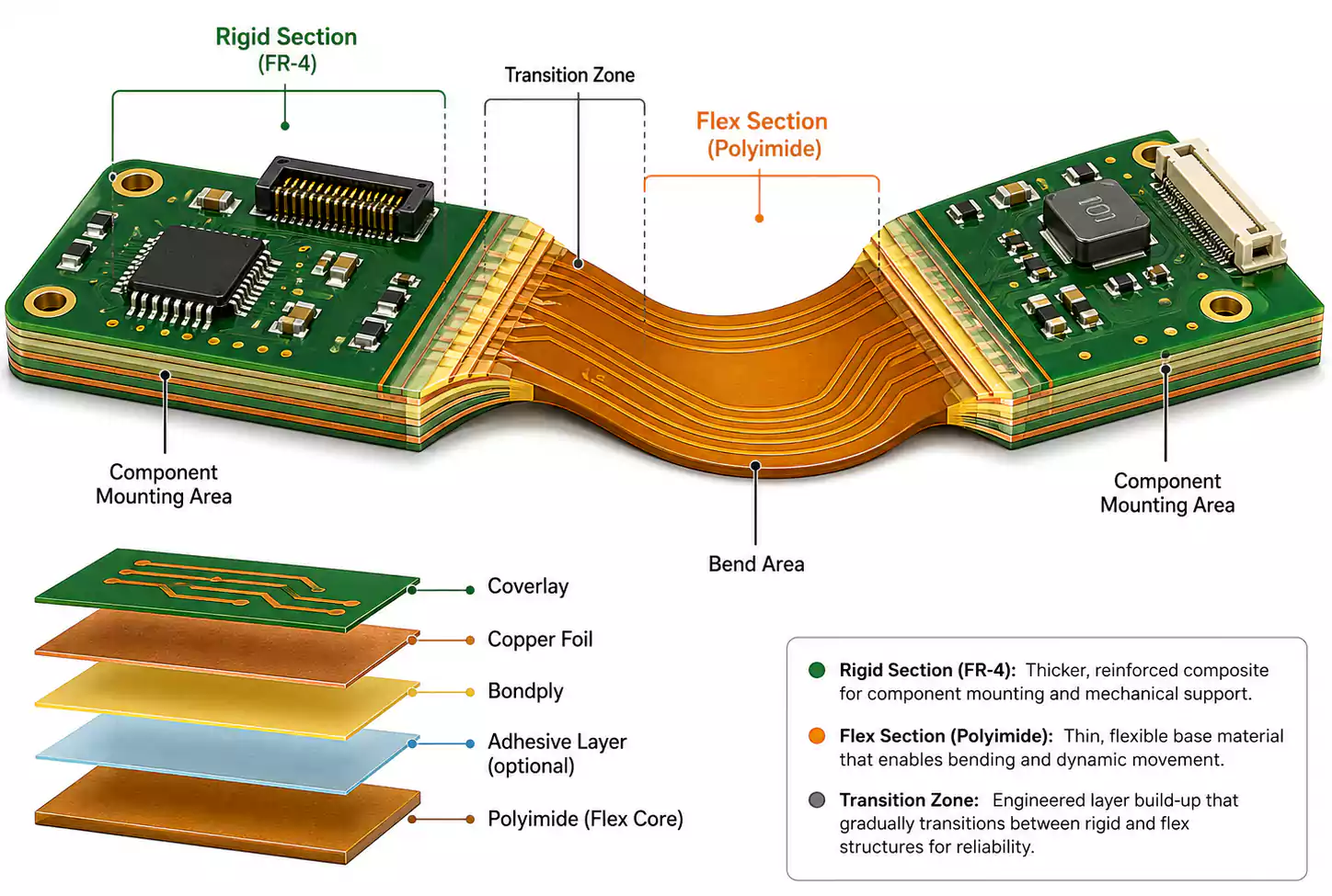
Rigid-flex PCB materials combine flexible polyimide layers in bend areas with rigid materials, typically FR-4, in component-mounting sections. This material system does more than define the board structure. It directly affects bend reliability, thermal stability, thickness, and manufacturability.
Successful rigid-flex PCB material selection is not about choosing one high-performance material in isolation. It is about balancing polyimide, copper foil, coverlay, adhesives, and bonding materials to fit the application, reliability target, and fabrication process.
Quick Takeaways
- Rigid-flex PCB materials should be selected as a complete material system rather than as isolated parts.
- Polyimide rigid-flex PCB constructions are the standard because PI combines flexibility, heat resistance, and electrical insulation.
- Adhesiveless copper-clad laminate is often preferred for high-density, high-reliability builds.
- Rigid-flex PCB coverlay protects flex conductors and supports bend durability.
- Bondply rigid-flex PCB structures depend on the proper selection of bonding sheets for lamination quality and flex performance.
- Material choices directly affect through-hole reliability, desmear, thickness, bend life, and manufacturing yield.
Why Rigid-Flex PCB Materials Matter More Than in Standard PCBs
Material selection in a conventional rigid PCB often centers on Tg, board thickness, copper weight, or solder mask.
Rigid-flex design is different.
A rigid-flex board combines rigid and flexible regions into a single integrated structure, so the materials must perform together during both manufacturing and use. Designers need to think about dielectric thickness, copper thickness, adhesive behavior, coverlay construction, bondply flow, and compatibility with lamination, drilling, and desmear processes.
This is also why two products can both be called rigid-flex while using very different material strategies. One design may prioritize long-term reliability in aerospace or industrial equipment. Another may prioritize thinness and density in a mobile device. In both cases, the material system determines how well the board will actually perform.

Polyimide Rigid-Flex PCB Design Starts With the Right PI Thickness
Polyimide is the foundation of most rigid-flex PCB materials systems.
A polyimide rigid-flex PCB uses PI as the primary dielectric in the flex region because it provides the combination of flexibility, electrical insulation, and thermal resistance needed for repeated processing and long-term field use.
One of the first decisions in rigid-flex PCB material selection is whether the design needs thicker or thinner polyimide.
Thick PI vs. Thin PI
| Thicker PI (>50 μm) | Aerospace, military, high-reliability products | Better process stability and durability |
| Thinner PI (<50 μm) | Consumer electronics, compact HDI products | Lower thickness and improved miniaturization |
Thicker polyimide is usually a better fit for designs that prioritize reliability, durability, and process stability. Thinner polyimide is more attractive in compact products where low profile and dense packaging are more important.
The key point is that thinner is not always better. In many reliability-driven designs, thicker PI provides a wider process window and stronger long-term performance.
Why Adhesiveless Copper Clad Laminate Is So Important in Rigid-Flex PCB Materials
Among all rigid-flex PCB materials, adhesiveless copper clad laminate is one of the most important for modern high-performance designs.
Compared with adhesive-based materials, adhesiveless systems generally provide:
- higher heat resistance
- lower thermal expansion
- better dimensional stability
- thinner final constructions
Those benefits matter because rigid-flex boards often go through multiple thermal cycles, complex lamination steps, and demanding drilling and plating operations.
The value of adhesiveless copper clad laminate is not just that it removes one adhesive layer. It changes how the whole structure behaves. Lower thermal expansion improves registration and dimensional control. Higher heat resistance helps the board withstand repeated processing. Reduced thickness makes the material especially attractive for thin, compact, and high-density rigid-flex builds.
Where Adhesiveless Copper Clad Laminate Is Most Useful
This material is especially valuable in:
- industrial HDI rigid-flex PCB designs
- medical electronics
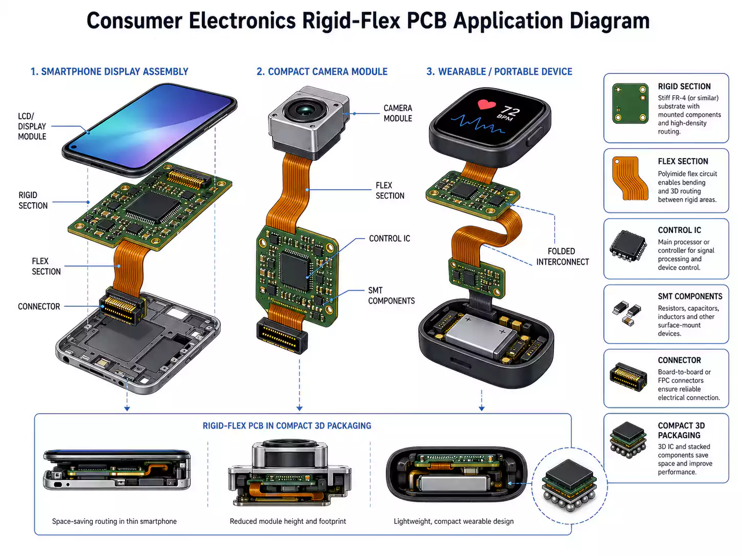
- compact camera modules
- display assemblies
- mobile devices
- other high-density products where thickness and reliability both matter
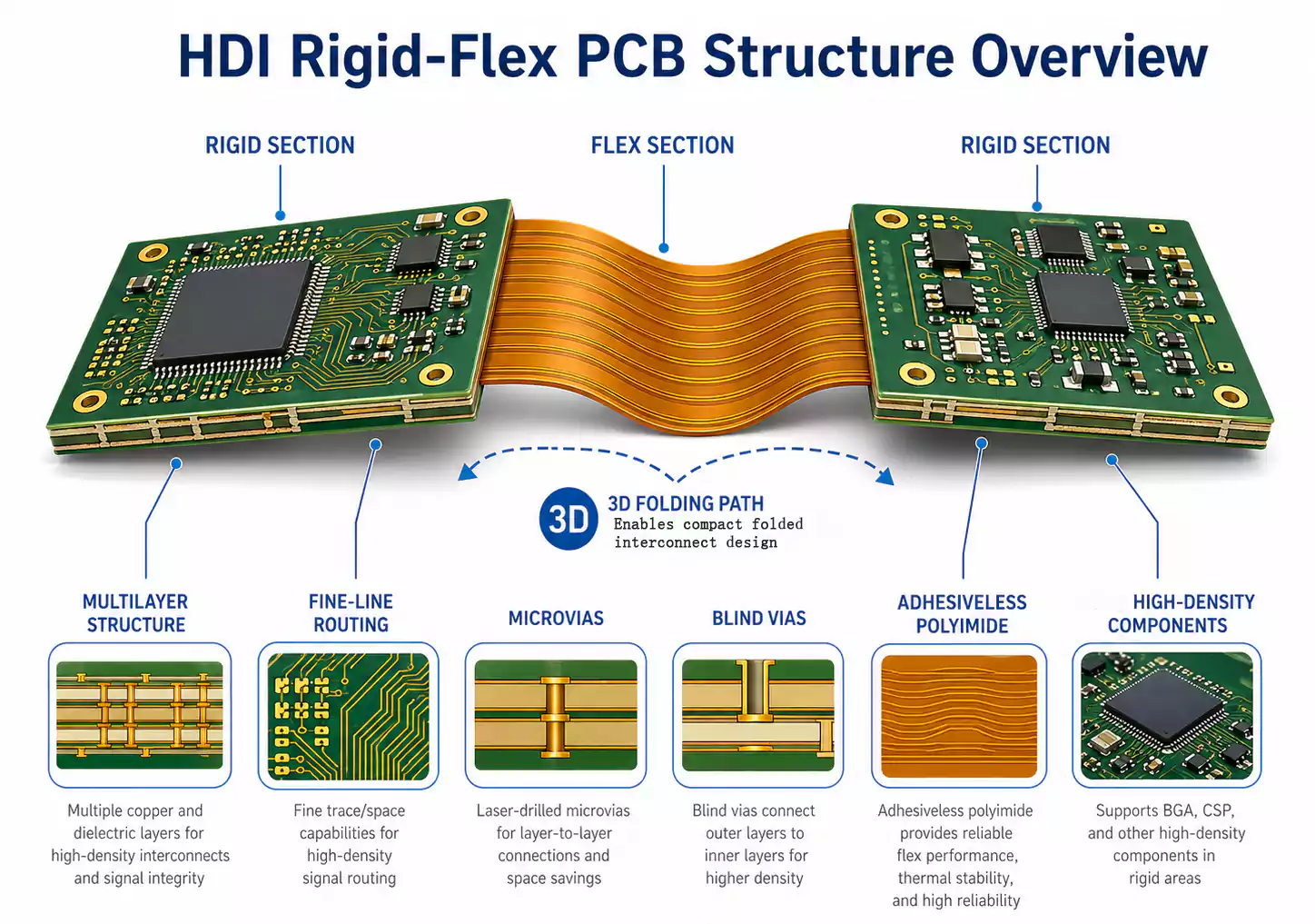
In many of these applications, adhesiveless material is paired with microvias, blind vias, and fine-pitch routing to support dense layouts without sacrificing too much process stability.
Copper Foil Also Affects Flex Reliability
Copper is not just the conductor in a rigid-flex board.
It also affects flex life.
In bending regions, copper must survive mechanical strain while still carrying current. That means copper selection is part of rigid-flex PCB material selection, not just an electrical detail.
In general:
- Thinner copper reduces strain concentration.
- Thinner copper works better with a thinner dielectric in the bend regions.
- Total flex thickness has a major impact on bend reliability.
For designs that involve repeated bending, copper becomes a mechanical reliability issue as much as an electrical one.
Rigid-Flex PCB Coverlay: More Than a Surface Protection Layer
A rigid-flex PCB coverlay does much more than cover exposed conductors.
It is part of the protection system for the flex region, helping shield the circuit from:
- moisture
- abrasion
- handling damage
- mechanical stress during bending
This matters because flex sections cannot simply use rigid-board protection logic. The protective layer must move with the flex material. If it cannot, it may lead to stress and early failure.
That is why coverlay is widely used in flex regions, while bend areas are carefully designed so that bonding materials do not unnecessarily restrict movement.
Why Coverlay Choice Matters
A good rigid-flex PCB coverlay can improve:
- conductor protection
- bend durability
- insulation performance
- surface reliability in harsh environments
Modern hot-melt polyimide coverlay systems can also reduce drill smear and support thinner constructions. The tradeoff is that these materials may require higher processing temperatures and tighter manufacturing control.
Bondply Rigid-Flex PCB Structures Depend on Proper Layer Bonding
A bondply rigid-flex PCB structure depends heavily on the selection and use of the bonding layers.
Bondply is not just there to hold layers together. It also influences:
- lamination flow
- gap filling
- Overall thickness control
- rigid-to-flex transition quality
- How much freedom does the flex region retain during bending
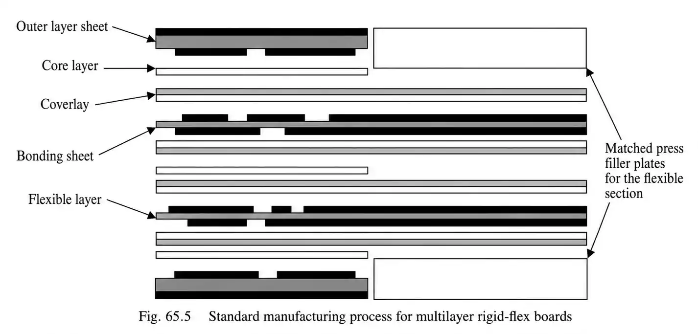
In multilayer rigid-flex boards, bondply is often pre-opened in the flex area to allow the structure to bend more naturally. In more complex designs, low-flow bondply, vacuum lamination, and support materials are used to improve fill and reduce voids.
Why Bondply Selection Matters
Bondply becomes especially important when the design includes:
- multilayer flex regions
- short bend zones
- complex rigid-to-flex transitions
- high-density stackups
- thin constructions with tight thickness targets
In these cases, bondply is not just a bonding material. It is part of the structural design.
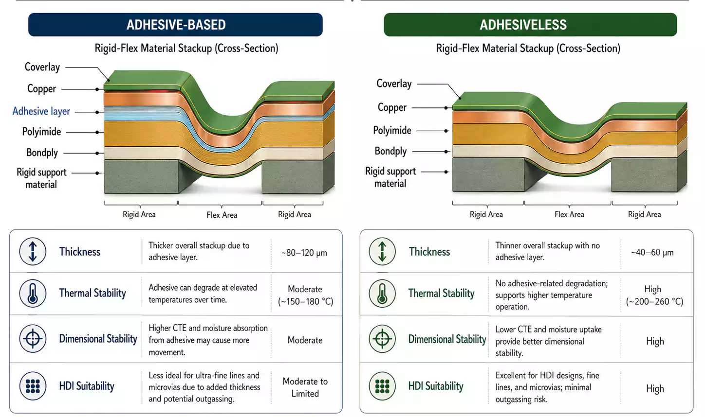
Adhesive-Based vs. Adhesiveless Materials in Rigid-Flex PCB Material Selection
This is one of the most important comparisons when selecting rigid-flex PCB materials.
Adhesive-Based Systems
Common adhesive families include:
- Acrylic adhesives: usually offer stronger bond strength, but lower heat resistance and higher shrinkage
- Epoxy adhesives: usually offer better heat resistance, but longer cure times and slightly lower bond strength
Adhesiveless Systems
Adhesiveless systems are usually preferred when the design needs:
- better thermal stability
- better dimensional stability
- lower overall thickness
- better support for fine features
- Improved consistency in demanding builds
Quick Comparison
| Adhesive-Based | Strong bonding options, familiar process routes | More thermal expansion, more shrinkage risk, possible desmear sensitivity |
| Adhesiveless | Better thermal stability, thinner build, stronger fit for HDI | May require tighter process control and different sourcing |
For many high-density or high-reliability designs, adhesiveless rigid-flex PCB materials are a better long-term fit.
How Rigid-Flex PCB Materials Affect Manufacturing
Rigid-flex PCB materials directly shape the manufacturing window.
A typical build may include:
- double-sided flexible copper-clad material
- coverlay over flex conductors
- pre-opened bondply in flex zones
- routed or depth-controlled rigid outer layers
- lamination, drilling, plating, and final forming
Each material contributes its own heat behavior, moisture sensitivity, and flow characteristics. Those differences affect the build's stability.
Key Manufacturing Effects of Material Choice
1. Lamination behavior
Materials influence pressure distribution, flow, and void filling.
2. Moisture control
Pre-baking matters because moisture can reduce lamination quality and hurt hole reliability.
3. Drill smear and desmear
Some material systems are much more sensitive than others.
4. Dimensional control
Thin flex materials can deform more across repeated thermal cycles.
A rigid-flex board may look simple on a drawing, but manufacturability often depends on whether the material set supports a realistic process window.
Through-Hole Reliability: Where Material Selection Becomes Critical
One of the most important reasons to choose the right rigid-flex PCB materials is the reliability of plated-through holes.
This is not just a drilling problem or a plating problem.
It is a material-system problem.
Through-Hole Reliability Depends On:
- drilling stability
- moisture removal before drilling
- desmear compatibility
- interface cleanliness
- plating adhesion
Traditional potassium permanganate desmear can be problematic in some rigid-flex constructions, especially when acrylic adhesive systems are involved. Adhesive-layer swelling can reduce hole reliability and narrow the process window.
That is why plasma desmear is often a better fit for rigid-flex PCB material selection. It can remove residue more effectively while causing less damage to adhesive-related interfaces.
For high-reliability products, plated hole-wall copper requirements are also higher. In those cases, the material system and the desmear method must work together to support reliable copper-to-inner-layer connections.
Bend Reliability Also Depends on Materials
Rigid-flex boards are often used because they allow folding and 3D packaging.
That makes bend reliability a core design target.
Material thickness, copper thickness, interlayer bonding strategy, and flex-layer length all influence how strain is distributed during bending.
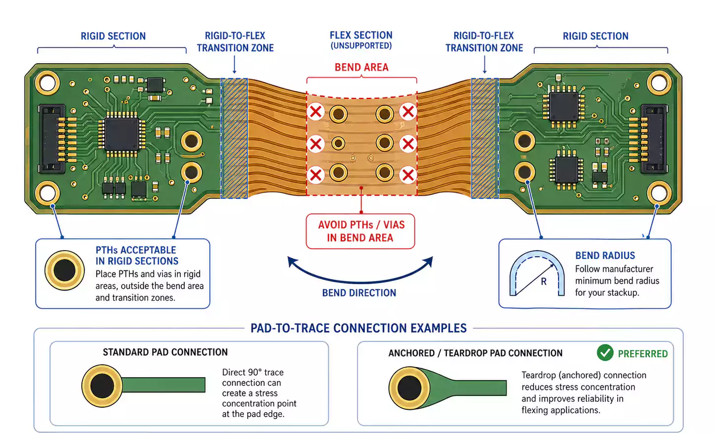
Important Bend-Reliability Principles
- Thinner materials usually improve bend performance.
- Thinner copper and thinner dielectric reduce strain concentration.
- Unbonded flex-layer structures can improve flexibility.
- Short bend areas need more careful layer-length management.
- Bookbinder-style layer design can improve reliability in short bend zones.
This is why a material guide for rigid-flex PCB design should never focus only on dielectric names. Bend behavior depends on the full material structure.
Material Selection by Application
Different products need different rigid-flex PCB materials.
| Aerospace / Military | Thicker PI, conservative structures, heavier hole-wall copper | Long-term reliability |
| Industrial / Medical HDI | Thin adhesiveless PI, fine lines, microvias, blind vias | High density with reliability |
| Consumer Electronics | Thin materials, reduced thickness, low-profile rigid areas | Thinness, density, and cost balance |
Aerospace and Military
These designs usually favor thicker PI and more conservative material systems because long-term reliability matters more than extreme miniaturization.
Industrial and Medical HDI
These applications often need thin adhesiveless materials, fine lines, and microvias, but still require strong process control and reliable interconnects.
Consumer Electronics
Phones, camera modules, and display products usually prioritize thin materials, lower total thickness, and efficient large-scale manufacturing.
FAQ
What are the best materials for rigid-flex PCB design?
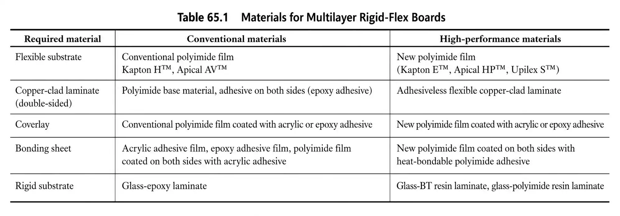
The best materials for rigid-flex PCB design depend on the application. In many cases, the answer includes polyimide, adhesiveless copper-clad laminate, coverlay, and bondply, selected as a matched system.
How do you choose rigid-flex PCB materials?
You choose rigid-flex PCB materials by balancing reliability, thickness, bend requirements, manufacturing capability, and cost. That is why rigid-flex PCB material selection should always be tied to the stackup and process route.
What is the role of polyimide in a rigid-flex PCB?
Polyimide is the primary flex dielectric. It provides flexibility, insulation, and thermal resistance in the bend region.
Why is adhesiveless copper-clad laminate preferred in high-density rigid-flex PCB?
Because it usually offers better thermal stability, better dimensional stability, and thinner constructions that support fine features and microvias.
What does rigid-flex PCB coverlay do?
It protects flex conductors from abrasion, moisture, and mechanical stress while supporting long-term bend reliability.
What is bondply in a rigid-flex PCB?
Bondply is the bonding material used between layers. It affects lamination flow, gap filling, thickness control, and bend-region behavior.
Conclusion
Rigid-flex PCB performance depends on the full material system, not on any single material alone. Polyimide, copper construction, coverlay, and bondply each influence bend reliability, dimensional stability, thickness, and manufacturability.
The right material stack is the one that fits the product’s structure, reliability requirements, and fabrication process. In rigid-flex design, good material selection is less about choosing the most advanced option on paper and more about choosing a system that can be built consistently and perform reliably in the end product.
For teams evaluating rigid-flex stackups and material options, FastTurn PCB can support early manufacturability review and design planning.
