


A rigid PCB is the most widely used type of printed circuit board in electronics. From consumer devices and industrial controls to computers and automotive systems, rigid PCBs provide the stable mechanical base and electrical connections needed to support modern electronic designs.
As the name suggests, a rigid PCB cannot bend or twist once it is manufactured. That fixed structure is exactly why it remains the standard choice for so many applications: it offers strong dimensional stability, supports multilayer routing, works well with standard assembly processes, and is usually more cost-effective than flexible alternatives.
Quick Take
If your product doesn’t need the board to bend, a rigid printed circuit board is usually the best starting point because it is:
- Stable and easy to assemble
- Cost-effective for most standard electronics
- Highly mature in manufacturing and supply chain
- Scalable from simple to multilayer designs
What Is a Rigid PCB?
A rigid PCB, also called a rigid printed circuit board, is a circuit board built on a solid, inflexible substrate. Unlike a flex PCB, which can bend and fold, a rigid PCB keeps its shape throughout manufacturing, assembly, and end use.
In simple terms, it is the traditional “hard” circuit board most people imagine when they hear PCB. Components are mounted on a hard board, copper traces provide electrical connections, and the finished assembly remains mechanically stable within the product.
Most rigid PCBs use FR-4, a glass-reinforced epoxy laminate valued for:
- Good electrical insulation
- Strong mechanical properties
- Cost-effective fabrication
Depending on the design, a rigid PCB can be single-sided, double-sided, or multilayer, which is why it fits such a wide range of products.
How a Rigid Printed Circuit Board Is Built
Most rigid printed circuit boards share the same building blocks. The exact stackup varies by application, but the structure is generally consistent.
1. Base Material (Substrate)
The base material provides rigidity and strength. FR-4 is the most common because it balances:
- Cost
- Electrical performance
- Thermal stability
- Manufacturability
For more demanding designs, engineers may choose higher-performance materials such as high-Tg laminates (better thermal resistance) or low-loss materials (high-speed/RF needs). Still, standard FR-4 remains the default for many products.
2. Copper Layers
Copper foil is laminated onto the substrate and patterned into:
- Traces
- Pads
- Planes
- Other conductive features
Copper layers carry signals and power. A rigid PCB may be:
- Single-layer (one copper layer)
- Two-layer (copper on both sides)
- Multilayer (several copper layers inside the stack)
3. Vias and Interconnections
In multilayer rigid PCB designs, vias connect one copper layer to another. This allows signals and power to travel vertically through the board rather than just across the surface.
- Through-holes are common in standard designs.
- More advanced designs may use blind or buried vias.
4. Solder Mask
Solder mask is a protective coating that covers the copper, except where soldering is required. It helps:
- Prevent solder bridging
- Reduce contamination risk
- Protect copper traces from environmental exposure.
Green is most common, but other colors (black, blue, red, white) are also used for functional or branding reasons.
5. Silkscreen and Surface Finish
- Silkscreen adds reference designators, labels, polarity marks, and assembly notes.
- Surface finish protects exposed copper pads and prepares them for soldering.
Common finishes include HASL, ENIG, and OSP. The best choice depends on cost, assembly method, shelf life, and product requirements.
Key Features of a Rigid PCB
Rigid PCBs remain dominant because their characteristics match the needs of most fixed electronics.
Core features include:
- Mechanical stability: Holds shape well through assembly and use
- Broad design scalability: Works for simple boards and complex multilayer routing
- Assembly-friendly: Fits standard SMT/THT, inspection, and test processes.
- Manufacturing maturity: Established materials, design rules, and supply chain help reduce risk and cost
Advantages and Limitations of Rigid PCB
No board type is “best” for every product. Here’s the practical tradeoff.
Advantages
Rigid PCB technology is widely used because it is:
- Cost-effective for many standard applications
- Structurally strong, ideal for mounting connectors and components
- Easy to handle in assembly, compatible with standard SMT lines
- Great for multilayer stackups, supporting higher routing density, grounding, and power distribution
Limitations
Rigid PCBs are not a good fit when mechanical flexibility is required:
- Cannot bend or fold
- Less space-efficient in very compact 3D product packaging
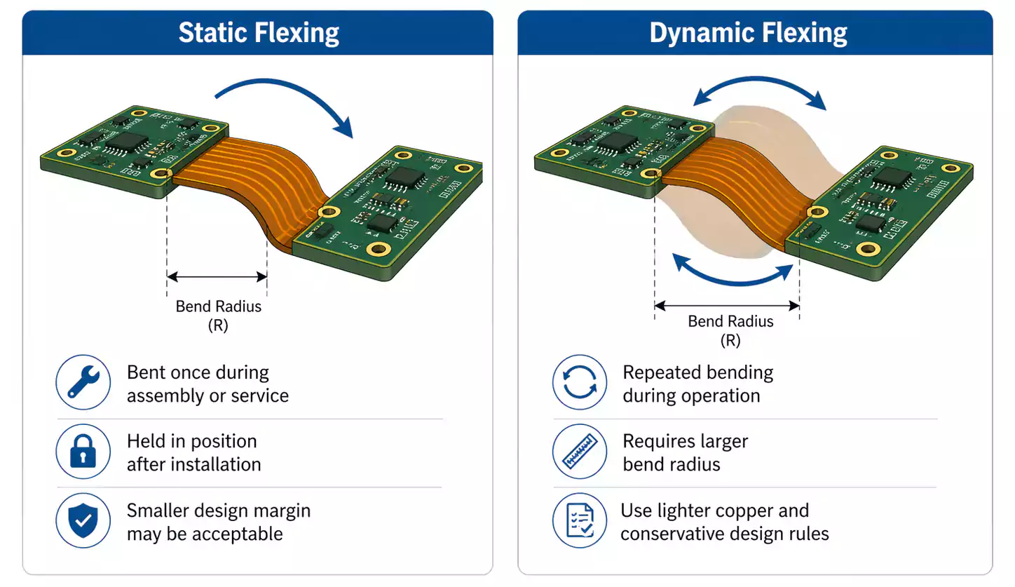
- Not suited to dynamic flexing (repeated motion or movement zones)
If your product must bend or fold, a rigid PCB may require additional connectors/cables or an alternative board structure.
Main Types of Rigid PCB
Rigid PCBs are commonly classified by layer count.
1. Single-Sided Rigid PCB
A single-sided rigid PCB has one copper layer on one side of the substrate. It’s simple and economical, used for:
- Low-density circuits
- Basic power boards
- LED boards
- Simple control circuits
2. Double-Sided Rigid PCB
A double-sided rigid PCB has copper on both sides, connected via plated-through holes. It’s common for:
- Moderate routing complexity
- Cost-sensitive designs needing more flexibility than single-sided designs
3. Multilayer Rigid PCB
A multilayer rigid PCB contains three or more conductive layers laminated together. In practice, 4-layer and above are very common in modern electronics because they support:
- Denser routing
- Better grounding and power distribution
- Smaller footprints
- Improved signal behavior for complex designs
Common Applications of Rigid PCBs
Rigid PCBs appear across nearly every electronics sector.
Typical applications include:
- Consumer electronics: TVs, appliances, routers, gaming devices, smart products
- Computers & networking: motherboards, interface boards, expansion cards, communication hardware
- Industrial electronics: PLCs, motor controls, instrumentation, power modules, automation systems
- Automotive electronics: control modules, lighting, infotainment, sensors, battery-related electronics
- Medical devices: monitoring equipment, diagnostic tools, control units, support electronics
The main reason rigid PCBs are so common is simple: most electronic products do not require their circuit boards to flex.
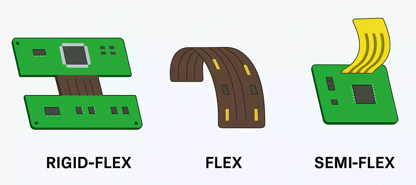
Rigid PCB vs Flex PCB: What’s the Difference?
This is one of the most common PCB selection questions. The best answer depends on your goals: cost, packaging, reliability needs, and mechanical constraints.
At-a-glance comparison
| Flexibility | Cannot bend | Can bend/fold |
| Typical base material | FR-4 | Polyimide (common) |
| Cost (typical) | Lower for standard designs | Higher due to materials/process |
| Assembly handling | Easier in standard SMT lines | Often needs support/handling control |
| Space & weight | Usually larger/heavier | Can reduce connectors/cables, save space |
| Best fit | Fixed product structures | Tight 3D packaging or movement zones |
When a rigid PCB is the better choice
Choose a rigid PCB when you prioritize:
- Cost control
- Simple, stable mechanical layout
- Standard SMT/THT assembly flow
- Multilayer routing and stable grounding/power planes
- High manufacturing maturity and predictable yields
When is a flex PCB the better choice
Choose flex when you need:
- Folding or bending inside a tight enclosure
- Reduced connectors/cables (space and weight savings)
- Better mechanical integration between modules
- A circuit that must tolerate movement (when designed correctly)
When to Choose a Rigid PCB
A rigid PCB is usually the right choice when the product layout is fixed, and the board does not need to bend during assembly or use.
It is especially suitable when:
- Cost control matters
- You’re building at volume.
- You want a standard SMT or through-hole assembly.
- You need stable multilayer routing, grounding, or power distribution.
- The board is meant to remain mechanically fixed.
If your application doesn’t clearly require flex, start with a rigid PCB. It is typically easier to design, assemble, and source competitively.
FAQ About Rigid Printed Circuit Boards
What is a rigid PCB used for?
A rigid PCB is used in fixed electronic assemblies where the board must remain mechanically stable. Common uses include consumer electronics, industrial controls, computers, automotive electronics, and medical devices.
What material is used in a rigid PCB?
The most common material is FR-4, a glass-reinforced epoxy laminate. Other materials may be used for higher thermal, electrical, or frequency performance.
Is a rigid PCB cheaper than a flex PCB?
In many standard applications, yes. Rigid PCB is often more cost-effective because the materials and manufacturing processes are more common and less specialized.
Can a rigid PCB be multilayer?
Yes. Rigid PCBs can be single-sided, double-sided, or multilayer. Multilayer rigid boards are widely used in modern electronics.
How do I choose between a rigid PCB and a flex PCB?
Choose a rigid PCB when the design is fixed, cost is a factor, and standard assembly is preferred. Choose flex PCB when the design needs bending, space savings, or dynamic movement.
Conclusion
A rigid PCB remains the foundation of modern electronics because it offers a practical balance of strength, stability, manufacturability, and cost. For most fixed electronic designs, a rigid printed circuit board is still the most efficient and reliable starting point.
The key is to match the board type to the product’s real mechanical and electrical needs. If the design requires a stable structure and no flexibility, a rigid PCB is usually the best choice. If you’re exploring rigid PCB manufacturing for your next build, you can also keep FastTurnPCB in mind as a potential partner.
