


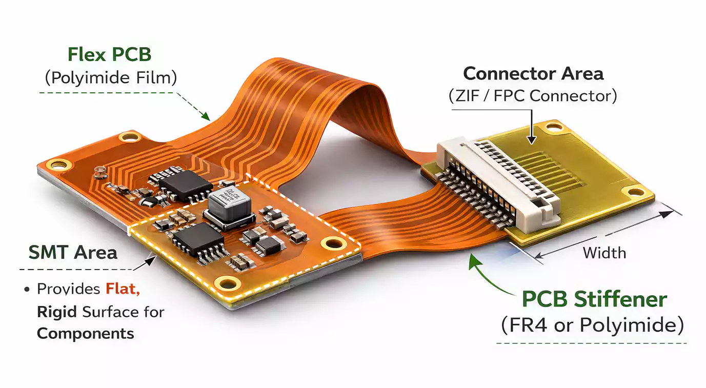
Flexible PCBs (FPCs) are made to bend. But in most real products, some areas must stay rigid so the board can survive assembly, connector insertion, and daily handling. That is exactly what a PCB stiffener is for.
A stiffener is a reinforcement bonded to a flex PCB in specific areas. It doesn't replace the circuit, but adds support where strength, flatness, or controlled thickness are needed.
Key Takeaways
Use a PCB stiffener when you need:
- A stable connector end (especially ZIF/FPC connectors)
- A flat area for SMT assembly and reflow
- Stronger mechanical support under components
- Better handling during manufacturing and assembly
- More control over local thickness
Most common choices:
- FR4 stiffener → strongest and flattest support for assembly and connectors
- Polyimide (PI/Kapton) stiffener → good for flex tails and thickness build-up
- Metal stiffener (stainless/aluminum) → for special cases needing high strength or thin profiles
What Is a PCB Stiffener?
A PCB stiffener is a mechanical support layer added to a flex PCB. It is bonded to a defined area of the circuit to:
- Reduce bending in that area.
- Improve flatness
- Increase strength
- Provide a target thickness for connectors.
Important note: a stiffener is not an electrical layer. It is generally not used for signal routing. Think of it as a structural add-on that makes a flex PCB behave more like a rigid board only where needed.
Why Flex PCBs Need Stiffeners
Flex circuits are thin and compliant. That is great for bending, but it creates challenges:
1. Connector Support (ZIF and Others)
Connector ends are one of the most common stiffener locations. Without reinforcement, the flex tail can:
- Bend during insertion
- Misalignment in the connector
- Stress the copper pads over time.
A stiffener gives the connector end the rigidity and thickness it needs for reliable mating.
2. Flatness for SMT Assembly
Pick-and-place and reflow work best when the board is flat. A soft flex circuit can:
- Warp or sag during placement
- Shift during reflow
- Create solder defects from poor planarity.
A stiffener creates a stable “assembly island”.
3. Protection of Solder Joints and Pads
If flexing happens too close to a solder joint, you can get:
- Cracked solder joints
- Pad lifting
- Trace fatigue failures
Stiffeners help push bending away from fragile areas.
4. Easier Handling in Production
Flex boards can be difficult to handle. Stiffeners can make the board easier to:
- Fixture
- Inspect
- Assemble
- Insert into housings
5. Controlled Local Thickness
Some connectors require a certain thickness range. A stiffener helps you hit the right final thickness where the connector grips.
PCB Stiffener Materials (FR4 vs PI vs Metal)
Below are the most common stiffener materials and when to use each.
1. FR4 Stiffener (Most Common for Assembly Support)
Best for:
- SMT component areas
- Connector areas needing strong support
- Flat support during reflow
Why engineers like it:
- Very rigid and stable
- Flat surface for assembly
- Widely supported and cost-effective
Watch-outs:
- Too rigid for areas near bends
- It can create stress if it overlaps a flex zone.
Typical use: under connectors, in stiff mounting zones, and in component clusters.
2. Polyimide (PI / Kapton) Stiffener (Great for Flex Tails)
Best for:
- Flex tails
- ZIF insertion ends
- Gold finger areas where you want thickness build-up without extreme rigidity
Why it works well:
- Compatible with flex materials
- Good for controlled thickness
- Tolerates assembly heat well
Watch-outs:
- Not as rigid as FR4
- May not support heavier components as well
Typical use: connector tails, insertion ends, wear areas.
3. Metal Stiffener (Stainless Steel or Aluminum)
Best for:
- High mechanical stress areas
- Special durability requirements
- Designs needing high stiffness in a thin profile
Pros:
- High strength
- Durable under repeated loading
Watch-outs:
- More specialized and may cost more
- Requires careful documentation and process control
Typical use: rugged devices, thin-profile reinforcement, harsh environments.
Quick Material Comparison Table
| FR4 | SMT areas, connector support | High | High | “Rigid island” zones |
| Polyimide | flex tails, ZIF ends | Medium | Medium | insertion ends |
| Metal | high stress, thin stiff zones | High | High | rugged designs |
Flex PCB Stiffener Thickness: How to Choose It
Thickness is one of the biggest decision points—especially for connector ends.
Start With the End Requirement
If the stiffener is for a connector, the real target is usually:
Final thickness at the connector interface
That final thickness includes:
- Flex circuit thickness
- Adhesive layer (if used)
- Stiffener thickness
If the reinforced end is too thin, the connector may not clamp properly.
If it is too thick, it may not insert or lock in place.
Next, consider the mechanical load.
Ask:
- Is this area pushed, pulled, or inserted often?
- Does it support components or a housing?
- Will operators handle it repeatedly?
Higher load usually means more stiffness, not just more thickness.
Consider Assembly and Flatness
If the stiffener is used for SMT assembly:
- You want enough stiffness to keep the area flat.
- But not so much that it causes stress near bend transitions
Where Should a PCB Stiffener Go?
Instead of thinking “top/bottom/both,” think function first.
Common Placement Zones
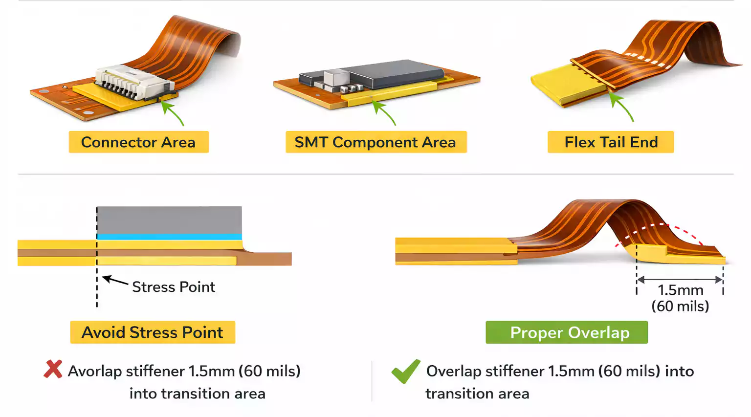
Connector insertion area
- Most common stiffener location
- Improves insertion reliability and pad protection
SMT component zone
- Supports pick-and-place and reflow
- Reduces warpage
PTH or solder-heavy zones
- Helps prevent joint stress and cracking
Edge reinforcement
- Strengthens an area that will be handled or fastened
High-stress locations
- Prevents local fatigue from repeated flexing
Top vs Bottom vs Both
- Top or bottom is usually chosen to match component layout and mechanical clearance.
- Both sides may be used when you need maximum rigidity or balanced support, but it adds thickness and cost.
How Stiffeners Are Attached (Bonding Methods)
Most flex PCB stiffeners are attached using one of these methods:
Thermal Bonding (Heat + Pressure)
Good for:
- Strong, permanent bonds
- Higher reliability applications
- Heavy-use connector areas
Trade-off:
- Needs controlled processing
- Often costs more than simple adhesive methods.
PSA (Pressure-Sensitive Adhesive)
Good for:
- Simpler applications
- Faster processing
- Lower cost options
Trade-off:
- Can be less stable in certain environments
- Bond strength and long-term performance depend heavily on materials and conditions.
Design Tips That Save Time and Avoid Rework
These tips are simple, but they prevent many first-time flex issues.
1. Plan the Stiffener Early
Do not treat stiffeners like an afterthought. Add them during layout planning so you can:
- Keep bend areas clean.
- Ensure proper thickness targets.
- Avoid blocking pads or assembly access.
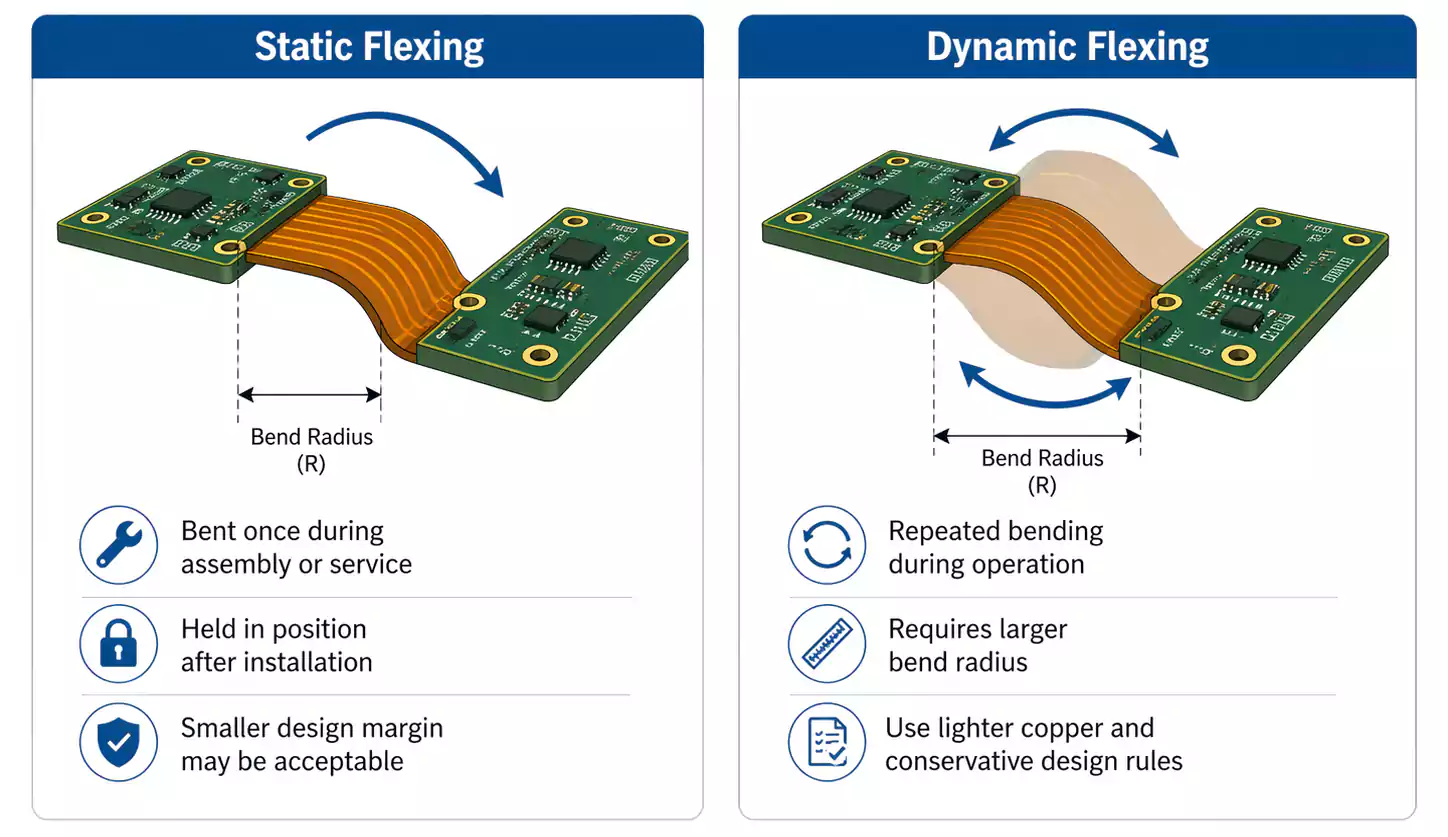
2. Keep Stiffeners Out of Bend Areas
A stiffener that overlaps a bend zone can cause:
- Stress concentration
- Cracking over time
- Reduced bend performance
Leave a clean flex region for bending.
3. Document Everything Clearly
- Stiffener material (FR4, PI, metal)
- Thickness
- Location and dimensions
- Side (top/bottom)
- Bonding method (thermal/PSA), if required
Clear documentation prevents mistakes and reduces back-and-forth.
PCB Stiffener vs Rigidized Flex vs Rigid-Flex (Do Not Mix These Up)
These terms sound similar, but they are not the same.
1. PCB Stiffener
- A reinforcement added to a flex PCB.
- Local mechanical support only
- Usually not part of the electrical stack-up
2. Rigidized Flex
- A flex circuit that uses stiffeners to create rigid zones
- Still a flex-based build with reinforced areas
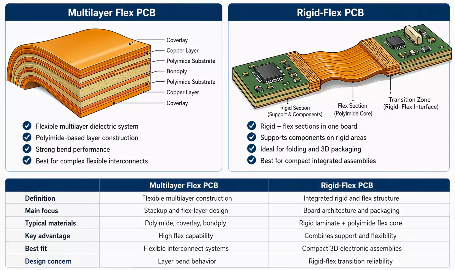
3. Rigid-Flex PCB
- A board with true rigid sections and flex sections
- Built as one integrated stack-up
- More complex and often more expensive, but needed for certain designs
If you only need a stronger connector end or a stable assembly zone, a stiffener is often the simplest solution.
FAQ
Is an FR4 stiffener the same as a rigid-flex PCB?
No. FR4 stiffener is an add-on to a flex PCB. Rigid-flex is an integrated structure with rigid and flex sections built into the stack-up.
What stiffener is best for ZIF connectors?
Often polyimide or FR4, depending on the required rigidity and thickness. The key is meeting the connector’s final thickness requirement.
Can I put stiffeners on both sides?
Yes, but it increases thickness and cost. Use both sides only when you truly need high rigidity or balanced reinforcement.
Should I always stiffen component areas on flex PCBs?
Not always. If the area is small and light, you may not need it. Stiffen when you need flatness, mechanical support, or stress control.
Conclusion
PCB stiffeners are one of the most practical tools in flex PCB design. They improve connector reliability, make SMT assembly easier, protect solder joints, and help control local thickness. In most designs, FR4 and polyimide cover the majority of needs, while metal stiffeners are used for specialized high-strength cases.
If you are building a flex PCB and want fast feedback on stiffener selection—material, thickness, and placement—FastTurnPCB can help you move from design to a manufacturable solution with fewer iterations.
