


In PCB mechanical drilling, PCB drill bits directly affect hole size accuracy, hole wall quality, chip evacuation, tool life, and overall process stability. To understand drilling quality, it is important to first understand PCB drill bit materials and PCB drill bit geometry.
This article explains the basic structure of PCB drill bits, including their material composition, key geometric parameters, and their relationships. It also shows how drill bit design influences drilling performance and final hole quality.
PCB Drill Bit Materials
A PCB drill bit typically consists of two parts:
- the cutting section
- the shank
To reduce cost, PCB drill bits with a diameter less than 3.175 mm are usually made as two-piece structures. In this design, the shank is typically made of stainless steel, the cutting section of cemented carbide, and the two parts are joined by welding.
Carbide PCB drill bits are common because cemented carbide provides excellent wear resistance at moderate cost, making it ideal for drilling abrasive laminates.
However, cemented carbide also has a major limitation. It is very hard but also brittle. If handling is improper or drilling conditions are not well controlled, the cutting section can develop edge chipping or other damage, which may reduce hole quality and shorten tool life.
PCB Drill Bit Geometry and Key Design Parameters
PCB drill bit geometry determines cutting performance, chip evacuation capability, rigidity, strength, and drilling quality. The most important parameters are outlined below.
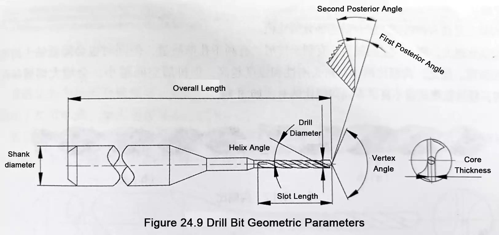
1. Drill Diameter
Drill diameter is the distance between the two outermost points on the margin of the cutting section.
This parameter directly determines the drilled hole diameter and is the most basic dimensional feature of PCB drill bits.
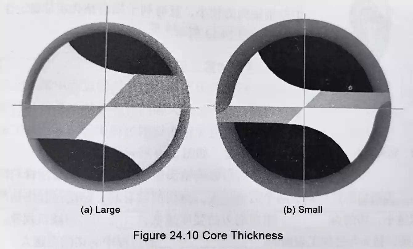
2. Web Thickness
Web thickness is the minimum distance between the two flutes, measured in a plane perpendicular to the drill axis.
It is one of the most important structural parameters of PCB drill bit geometry, because it directly affects:
- cutting load
- drill rigidity
- drill strength
- chip space
Increasing web thickness improves the drill bit's bending, torsional, and overall rigidity. However, the chip space becomes smaller, chip evacuation becomes more difficult, tool wear increases, and hole wall quality may be affected.
When web thickness is reduced, chip space increases and chip removal improves, but the drill bit becomes less rigid and more prone to breakage.
In practice, web thickness is a balance between strength and rigidity on one hand and chip-removal capacity on the other.
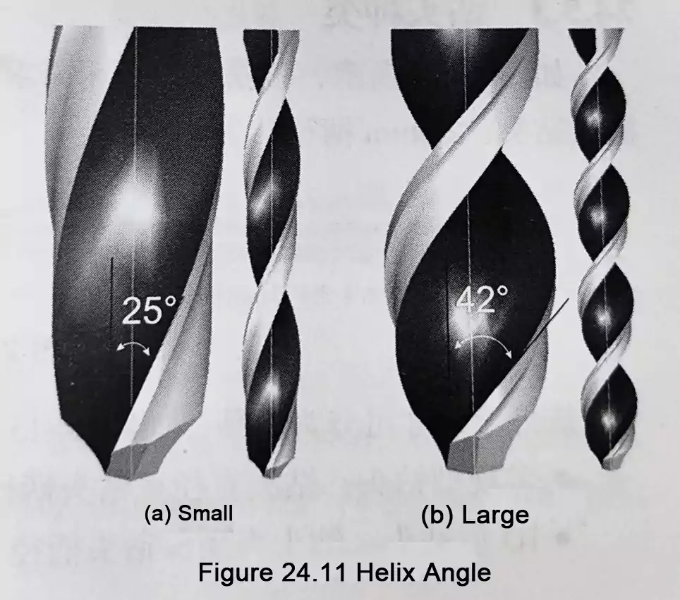
3. Drill Bit Helix Angle
The drill bit helix angle is the angle between the tangent of the flute helix on the outer cylindrical surface and the drill axis.
Because all points along the flute have the same lead, the helix angle is not identical at every point along the main cutting edge. It is larger near the margin and becomes smaller toward the center of the drill.
The drill bit helix angle is closely related to cutting sharpness and chip evacuation. In general:
- A larger helix angle gives a larger effective rake angle, a sharper cutting edge, and better chip evacuation.
- A smaller helix angle results in less aggressive cutting and weaker chip removal.
However, an excessively large helix angle also has drawbacks. It increases the chip flow path, reduces body rigidity, and weakens the cutting edge, making the drill more prone to edge chipping and wear during drilling.
For this reason, the helix angle must be selected to balance cutting sharpness, chip evacuation, and edge strength.
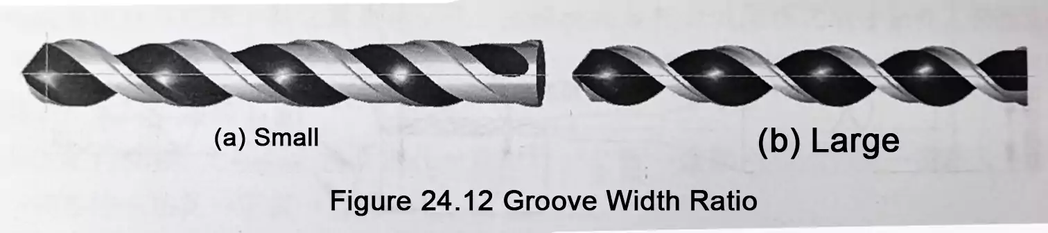
4. Flute-to-Body Ratio
The flute-to-body ratio refers to the ratio between the flute width and the drill body width.
This parameter mainly affects chip space and overall drill rigidity.
- A larger flute-to-body ratio provides more chip space and improves chip evacuation, thereby improving hole wall quality, but it also reduces drill rigidity and strength.
- A smaller flute-to-body ratio increases rigidity and strength, but reduces chip space. This can increase friction between the chips and the hole wall, potentially leading to poorer hole wall quality.
As a result, this part of the PCB drill bit geometry must also be balanced between chip evacuation performance and structural strength.
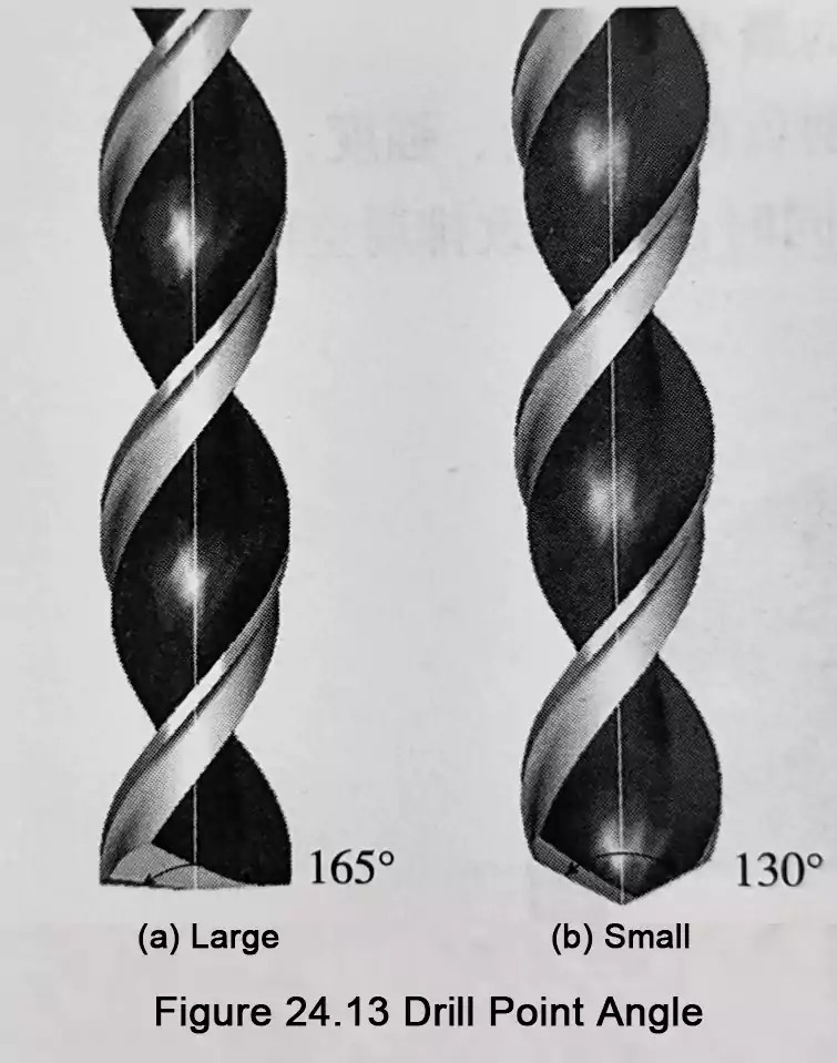
5. Drill Bit Point Angle
The drill bit point angle is the angle formed by the projection of the two main cutting edges onto a parallel plane.
The drill bit point angle affects the length of the main cutting edges, the cutting width, chip shape, and chip flow direction, thereby directly influencing drilling load and hole quality.
- A larger point angle tends to produce thicker, shorter chips. After leaving the cutting edge, these chips are discharged toward the drill's root, improving chip evacuation, but this increases the axial drilling force.
- A smaller point angle tends to produce spiral-shaped chips, which are harder to evacuate and may affect hole wall quality. However, axial force is lower, and hole positioning stability is generally better.
Point angle selection is therefore a balance among chip evacuation, axial force, and positioning stability.
6. Primary Relief Angle and Secondary Relief Angle
The primary relief angle is designed to prevent the primary flank surface from contacting the machined surface during drilling, thereby reducing axial force and frictional heat. The secondary relief angle is designed to prevent interference between the drill body and the machined surface.
These two relief angles affect the cutting sharpness, main cutting edge strength, and the contact area between the drill and the hole wall.
In general:
- Larger relief angles improve cutting action, reduce contact area, and lower cutting force, but they also reduce main cutting edge strength and increase the likelihood of edge chipping.
- smaller relief angles provide higher cutting edge strength, but increase the friction area and cutting force during drilling
The design of the primary and secondary relief angles, therefore, balances cutting sharpness, friction control, and edge strength.
Relationships Between PCB Drill Bit Geometry Parameters
The geometry of PCB drill bits is not designed to maximize a single property. Instead, it is an overall balance among rigidity, chip evacuation, cutting sharpness, and edge strength. The main tradeoffs are as follows.
1. Rigidity vs. Chip Evacuation
- Larger web thickness and a smaller flute-to-body ratio improve drill rigidity and strength, but reduce chip space.
- Smaller web thickness and a larger flute-to-body ratio improve chip evacuation, but reduce overall rigidity.
2. Sharpness vs. Edge Strength
- Larger drill bit helix angle and larger relief angles produce sharper cutting action and lower friction.
- However, they also reduce cutting-edge strength and increase the risk of chipping or edge damage.
3. Chip Evacuation vs. Axial Force
- A larger drill bit point angle improves chip evacuation, but increases axial force.
- A smaller drill bit point angle reduces axial force and improves positioning stability, but makes chip evacuation more difficult.
For this reason, PCB drill bit geometry varies depending on the application. Parameter selection should be matched to the laminate type, hole diameter, aspect ratio, stack height, and process requirements.
FAQ
1. Why are carbide PCB drill bits commonly used?
Because cemented carbide offers good wear resistance and relatively low cost, making it suitable for drilling abrasive PCB laminate materials.
2. What is the main limitation of cemented carbide?
It is very hard but brittle, so edge chipping can occur if handling or drilling conditions are improper.
3. Which parameter determines hole size?
Drill diameter directly determines the drilled hole diameter.
4. How does web thickness affect performance?
Web thickness affects rigidity, strength, and chip space. A thicker web improves strength but reduces chip evacuation space; a thinner web improves chip removal but lowers rigidity.
5. What does helix angle affect?
Helix angle mainly affects cutting sharpness and chip evacuation. A larger helix angle improves cutting and chip removal, but may reduce rigidity and edge strength.
6. What does point angle affect?
Point angle affects chip shape, chip flow direction, and axial force. A larger point angle improves chip evacuation but increases axial force.
7. Why are relief angles important?
Primary and secondary relief angles affect cutting sharpness, edge strength, friction area, and cutting force.
Conclusion
The material and geometry of PCB drill bits directly impact drilling quality.
From a materials standpoint, PCB drill bits commonly use a stainless-steel shank and a cemented-carbide cutting section. A carbide PCB drill bit offers good wear resistance and relatively low cost, but the material is also very hard and brittle.
Drill bit parameters interact and, together, determine drilling stability, tool durability, and final hole quality. Understanding PCB drill bit materials and PCB drill bit geometry is essential for drill selection and drilling process optimization.
