


77 GHz radar is a high-frequency millimeter-wave sensing technology widely used in automotive ADAS and industrial detection systems. Compared with legacy 24 GHz radar, it offers higher resolution, a smaller antenna, and stronger performance in modern sensing applications.
For PCB designers, this shift is not just about frequency. It directly changes how the board must be designed, especially regarding material loss, stackup structure, routing behavior, and manufacturing tolerances.
That is why a PCB material strategy that works at 24 GHz is often not enough at 77 GHz. As radar moves deeper into the millimeter-wave range, material selection becomes a much more critical part of overall system performance.
This article explains how 24 GHz and 77 GHz radar designs differ, and what those differences mean for PCB material selection.

Quick Answer
If you only need the short version, here it is:
- 24 GHz radar usually offers greater design flexibility and more cost-performance trade-offs.
- 77 GHz radar demands tighter control over loss, dielectric stability, copper roughness, routing geometry, and stackup structure.
- At 77 GHz, the PCB is no longer just a support structure. It becomes part of the RF system itself.
- Good radar PCB material selection is not just about Dk and Df. It also involves copper profile, thickness control, phase consistency, environmental stability, and manufacturability.
24 GHz vs. 77 GHz Radar at a Glance
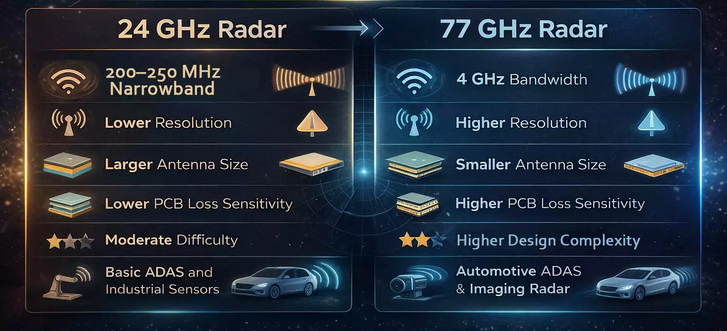
| Typical use | Legacy radar, simpler short-range systems | Modern ADAS, corner radar, long-range radar, imaging radar |
| Bandwidth potential | Lower | Much higher |
| Range resolution | Lower | Higher |
| Antenna size | Larger | Smaller |
| PCB loss sensitivity | Moderate | High |
| Tolerance sensitivity | Lower | Much higher |
| Material demands | More flexible | Much stricter |
| Stackup complexity | Often simpler | Often more advanced or hybrid |
What 77 GHz Radar Means for PCB Designers
Modern 77 GHz radar is not just a single RF path on a board. It is usually part of a dense, multi-channel, phase-sensitive system.
That matters because radar modules now support functions such as:
- adaptive cruise control
- automatic emergency braking
- blind-spot monitoring
- cross-traffic alert
- parking assistance
- high-resolution imaging radar
As radar systems become more advanced, the PCB must do more than just route signals. It must support:
- low-loss RF transmission
- stable phase behavior
- repeatable antenna performance
- tight dimensional control
- consistent multi-channel behavior
At 24 GHz, a design can often tolerate more electrical and manufacturing variation. At 77 GHz, that margin shrinks fast.
Why the Industry Moved from 24 GHz to 77 GHz
The move from 24 GHz to 77 GHz happened for good reasons.
Higher resolution
Wider available bandwidth allows radar to distinguish objects more precisely. That improves distance resolution and target separation.
Smaller antennas
A shorter wavelength means the antenna can be made much smaller for the same field of view and gain target.
Better suitability for modern ADAS
As automotive systems moved toward more advanced sensing, 77 GHz became the better fit for:
- long-range forward radar
- corner radar
- imaging radar
- higher angular resolution systems
Why 24 GHz and 77 GHz Do Not Use the Same Material Logic
This is where many articles tend to be too general.
A designer may assume that radar PCB material selection is just a matter of picking a “better” high-frequency laminate. But in reality, 24 GHz and 77 GHz often require different selection logic.
At 24 GHz
Material choice is often a balance of:
- acceptable RF loss
- manufacturing convenience
- cost control
- stable enough electrical behavior
For some shorter-path or lower-complexity designs, a more practical low-loss approach may be enough.
At 77 GHz
The focus shifts toward:
- lower insertion loss
- tighter phase consistency
- more stable dielectric behavior
- smoother copper surfaces
- thinner and better-controlled RF structures
- Higher manufacturing repeatability
In other words, 77 GHz is usually not just “more high frequency.”
It is a different design environment.
The Material Properties That Actually Matter
Many engineers start by looking at Dk and Df, which is correct, but incomplete.
Here are the properties that matter most.
1. Dielectric Constant (Dk)
Dk affects:
- transmission-line dimensions
- impedance
- antenna size
- electrical length
- phase behavior
At 77 GHz, Dk stability can matter as much as the nominal value itself. A material with a good published Dk number is not enough if that value shifts too much with temperature or frequency.
2. Loss Tangent (Df)
Df helps determine dielectric loss.
As frequency rises, dielectric loss becomes more important. At 77 GHz, even small differences in loss can affect:
- feed line efficiency
- receiver sensitivity
- signal integrity
- antenna system performance
That said, Df should not be evaluated alone. A material with low Df but poor manufacturing repeatability may still be the wrong choice.
3. Copper Roughness
This is one of the most overlooked variables in radar PCB design.
At 77 GHz, the condition of the conductor surface matters much more than many designers expect. Rougher copper increases conductor loss, especially in thin RF structures.
Copper roughness can influence:
- insertion loss
- phase consistency
- effective signal behavior at mmWave frequencies
This is one reason why two boards built on similar dielectric materials can still perform differently.
4. Thickness Control
Board thickness and dielectric thickness directly affect RF routing behavior.
At 77 GHz, small changes in dielectric thickness can shift impedance and phase more significantly than they would at lower frequencies.
Thickness control matters for:
- microstrip dimensions
- coplanar waveguide performance
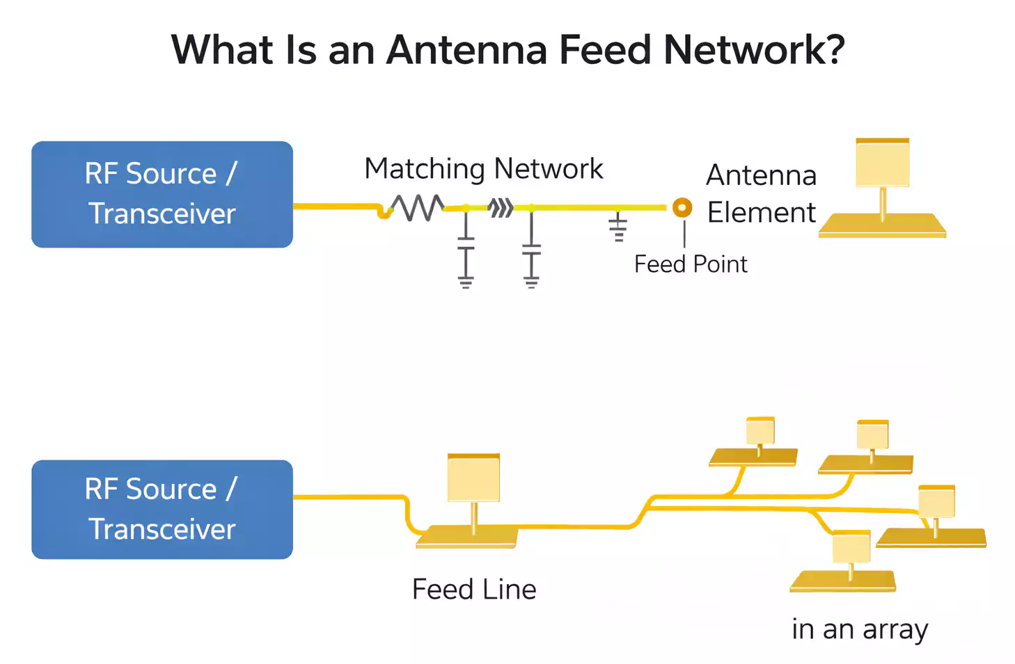
- antenna feed networks
- Overall RF repeatability
5. Environmental Stability
Radar boards often operate in demanding environments.
For automotive and industrial radar, the PCB material may need to tolerate:
- wide temperature swings
- humidity exposure
- long service life
- Repeated thermal cycling
A material that performs well in the lab may not be the best choice in a harsh real-world environment.
6. Manufacturability
This is where many material comparisons fall short.
A radar PCB material is not just chosen for electrical performance. It also has to fit the real production process:
- lamination
- drilling
- plating
- registration control
- yield stability
- cost at scale
The best material on paper is not always the best material for actual production.
Why Stackup and Routing Matter as Much as the Material
Material selection cannot be separated from the routing structure.
At 77 GHz, the routing method becomes part of the selection decision.
Common routing structures include:
- Microstrip
- Stripline
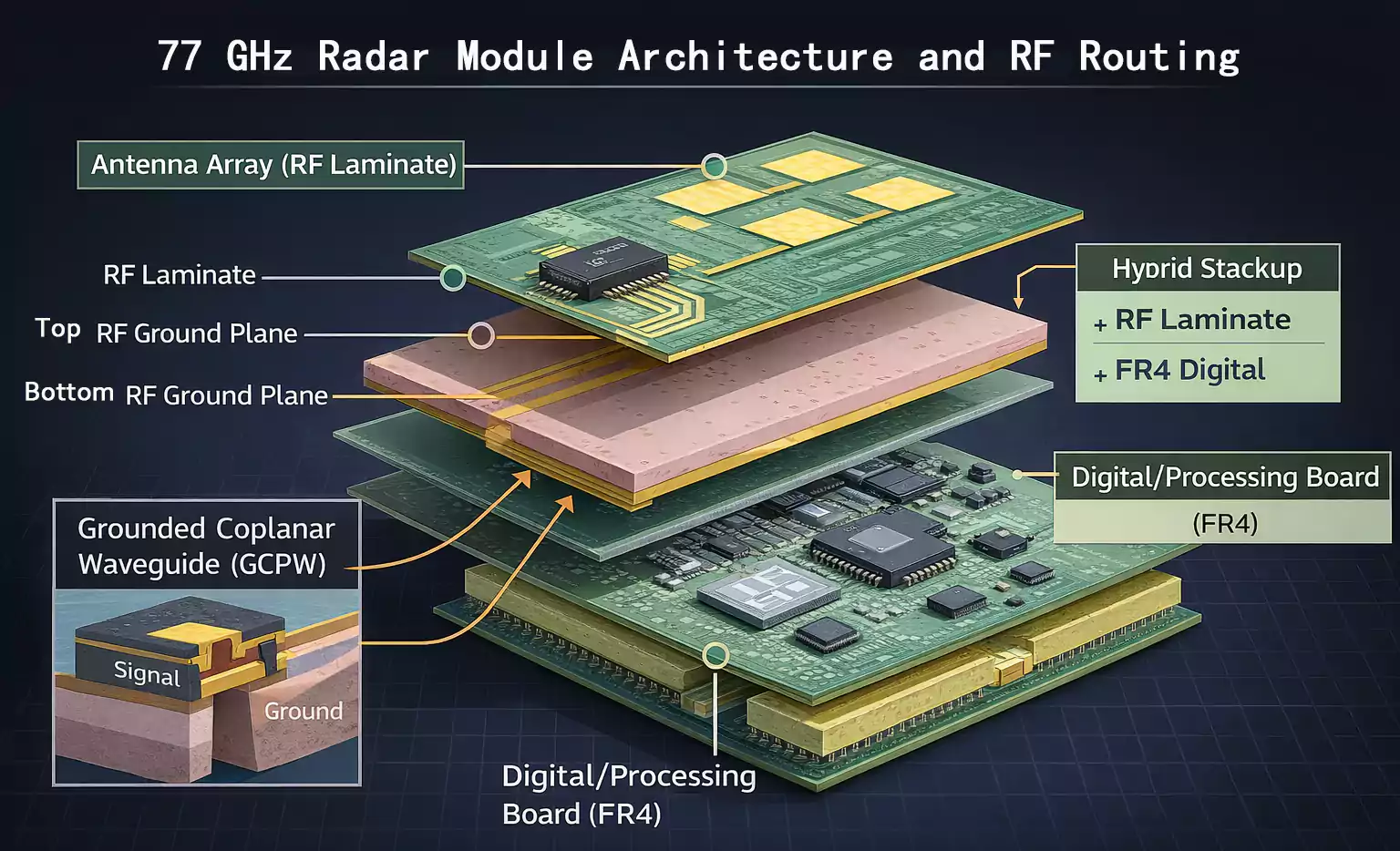
- Grounded coplanar waveguide (GCPW)
For many 77 GHz radar boards, grounded coplanar waveguide is especially attractive because it provides better control in compact RF routing environments.
What stackup planning must consider
A good radar stackup should account for:
- signal layer location
- reference plane continuity
- dielectric thickness
- routing geometry
- antenna integration
- RF isolation
- digital and power section separation
Why hybrid stackups are common
Not every layer on a radar board needs the same material.
In many designs:
- The RF or antenna layers use a low-loss high-frequency laminate.
- The digital, control, or power layers use FR-4 or another more economical material.
This hybrid approach helps balance:
- RF performance
- manufacturability
- total board cost
That is often a better solution than trying to build the entire board on a premium RF laminate.
Material Selection by Use Case
Instead of asking for the single “best” radar PCB material, it is better to ask what the application actually needs.
Cost-sensitive 24 GHz radar modules
These designs may prioritize:
- manageable cost
- process compatibility
- acceptable RF performance
- lower manufacturing complexity
In these cases, the best solution may be a practical low-loss material strategy rather than the lowest-loss laminate available.
77 GHz corner radar
Corner radar typically pushes the design toward:
- smaller structures
- tighter tolerances
- better phase consistency
- improved routing control
Material choice becomes more demanding, especially when the design includes board-mounted antennas or multiple RF channels.
77 GHz long-range radar
Long-range radar generally requires stronger performance in:
- link budget
- signal consistency
- low-loss transmission
- high repeatability
This often justifies a more advanced material and stack-up approach.
77 / 79 GHz imaging radar
This is one of the most demanding use cases.
These designs may involve:
- MIMO architectures
- high channel counts
- tighter angular resolution goals
- stronger dependence on phase alignment and channel consistency
In this case, material behavior and stackup execution are both critical.
Industrial and traffic radar
77 GHz radar is not limited to automotive use.
It is also used in:
- traffic monitoring
- intersection sensing
- industrial motion detection
- mobile equipment detection
These applications can introduce additional requirements for environmental durability and long-term stability.
A Practical Material Selection Workflow
A more useful way to choose radar PCB materials is to follow a decision sequence.
Step 1: Define the application
Start with the real system target:
- automotive or industrial
- short-, mid-, or long-range
- standard radar or imaging radar
- board-mounted antenna or external antenna
Step 2: Define the operating band and bandwidth
Clarify whether the design is:
- 24 GHz
- 76–77 GHz
- 77–81 GHz
This affects both performance goals and PCB difficulty.
Step 3: Define the board architecture
Decide early whether the system will use:
- a single-board approach
- a separate antenna board
- a hybrid stackup
- a split RF and digital structure
Step 4: Choose routing geometry
Select the routing structure based on the stackup and frequency:
- microstrip
- stripline
- grounded coplanar waveguide
Step 5: Match material behavior to system needs
Now evaluate the material based on:
- Dk
- Df
- copper roughness
- thickness control
- stability over the environment
- manufacturing compatibility
Step 6: Check manufacturability before finalizing
Before committing to the material, confirm that the PCB fabricator can support:
- the required tolerances
- the required copper structure
- the required stackup
- the required yield expectations
This step prevents many costly redesigns.
Common Mistakes in 77 GHz Radar PCB Material Selection
These mistakes often appear in real projects.
1. Looking only at Dk and Df
Those values matter, but they are not enough.
2. Treating 24 GHz and 77 GHz the same way
A strategy that works at 24 GHz may fail at 77 GHz.
3. Ignoring copper roughness
At mmWave frequencies, the copper profile can significantly affect loss.
4. Choosing a material without considering the routing structure
Material and transmission-line geometry must work together.
5. Ignoring thickness and tolerance sensitivity
Small physical changes matter more at 77 GHz.
6. Focusing on lab performance only
Real-world automotive and industrial conditions can expose weaknesses that are not obvious in early prototypes.
7. Choosing by brand name alone
A well-known material family does not automatically mean the best fit for your radar design.
24 GHz vs. 77 GHz Material Selection Priorities
| Cost flexibility | Higher priority | Still important, but less dominant |
| Low loss | Important | Critical |
| Dk stability | Important | Very important |
| Copper roughness control | Useful | Highly important |
| Stackup complexity | Moderate | Often high |
| Tolerance sensitivity | Moderate | High |
| Hybrid stackup value | Sometimes useful | Often very useful |
| Manufacturing repeatability | Important | Essential |
FAQ
What band is 77 GHz radar?
In automotive use, 77 GHz radar usually refers to the 76–81 GHz radar band.
Why did the industry move from 24 GHz to 77 GHz?
Because 77 GHz supports:
·wider bandwidth
·higher resolution
·smaller antennas
·more advanced ADAS performance
Is 77 GHz radar only for automotive use?
No. It is also used in traffic and industrial sensing applications.
Can FR-4 still be used in a 77 GHz radar module?
It can be used in some parts of the system, especially in hybrid designs, but it is often not the ideal material for the most RF-critical sections, such as antennas or feed structures.
Is the lowest-loss material always the best choice?
Not always. The best material must also fit the stackup, manufacturing process, yield target, and cost goal.
Final Takeaway
The move from 24 GHz to 77 GHz changes more than the radar frequency. It raises the demands on PCB materials, stackup design, routing control, and manufacturing consistency.
At 24 GHz, designers often have more room for compromise. At 77 GHz, small differences in loss, copper profile, dielectric stability, and board structure can have a much greater impact on performance.
That is why radar PCB material selection should never be based solely on laminate data. The right choice depends on how well the material, stackup, and routing strategy fit the actual radar architecture.
FastTurnPCB works with advanced RF and high-frequency PCB designs that require consideration of both electrical performance and manufacturability.
