

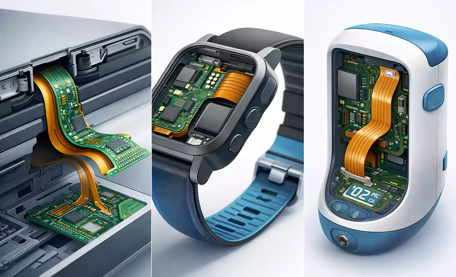


When engineers design a PCB, most attention naturally goes to schematics, routing rules, stackups, and signal paths. But behind every reliable electronic product lies a less glamorous—yet absolutely critical—foundation: the PCB material system.
Your choices in PCB substrate, resin, reinforcement, and specialty dielectrics directly influence reliability, signal integrity, thermal performance, manufacturability, and long-term product stability.
This guide breaks down the most commonly used PCB board material, the key electrical and thermal parameters you must understand, and practical engineering guidance for real-world product design.
Three Major Categories of PCB board material
In electronic packaging, PCB board material generally fall into three groups:
1. Reinforced Organic Materials
Typical example: glass-fiber reinforced epoxy (FR-4)
Used in: rigid PCBs, multilayer boards, HDI, general electronics
2. Non-Reinforced Organic Materials
Examples: polyimide film, PTFE film, flexible laminates
Used in: flexible PCBs, RF/microwave applications
3. Inorganic Materials
Examples: ceramics, alumina (Al₂O₃), aluminum nitride (AlN)
Used in: power modules, high-reliability automotive systems, multichip modules (MCMs)
Each category offers distinct benefits in electrical performance, thermal behavior, and mechanical stability. Material choice becomes especially critical in RF layouts, high-speed digital designs, high-layer-count boards, and harsh-environment applications.
Key PCB board material Parameters
Data sheets list many characteristics, but only a handful significantly impact PCB reliability and signal performance.
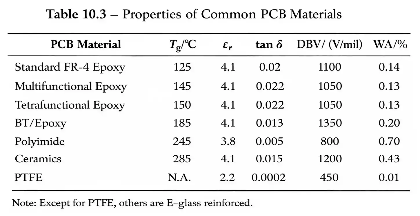
1. Glass Transition Temperature (Tg)
Tg is the point where resin shifts from a “glassy” to a “rubbery” state—beyond this, the material expands much faster.
Why Tg matters
- Thick, high-layer-count boards experience significant thermal stress during reflow and rework.
- Low Tg materials may cause:
- barrel cracking
- pad lifting
- internal delamination
Rule of thumb:
- Consumer electronics → standard Tg FR-4 is typically sufficient.
- High-layer count, industrial, automotive → high-Tg FR-4 or advanced resin systems
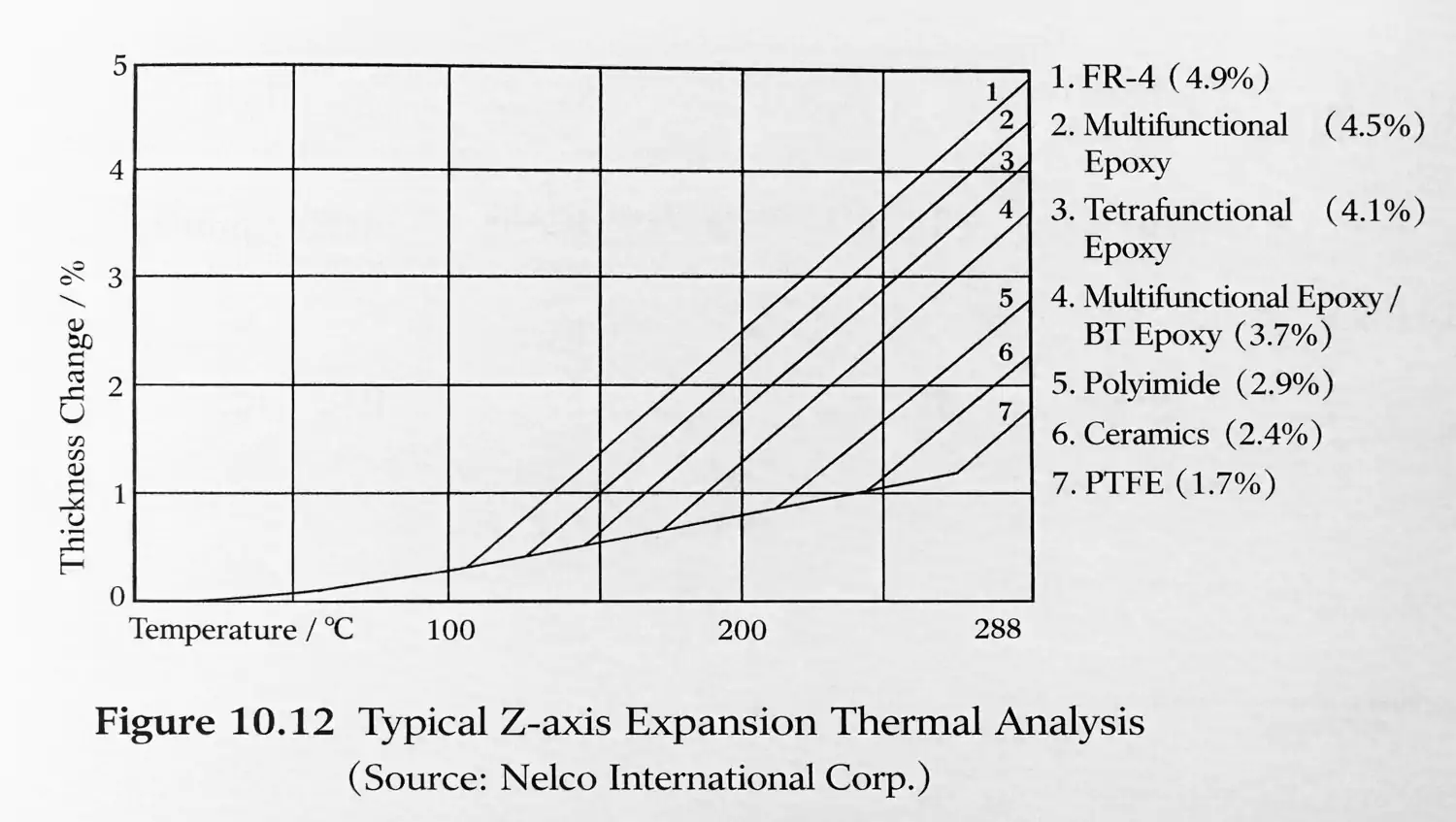
2. Coefficient of Thermal Expansion (CTE)
CTE describes the extent to which a material expands with temperature. PCB designers should care most about the Z-axis CTE, because that’s where plated-through holes experience stress.
Why Z-axis CTE matters
- Higher reflow temperatures in modern SMT processes
- Increasing PCB thickness and layer count
- Risk of:
- plated-through-hole (PTH) cracking
- Microvia reliability failures
Design tip:
For HDI boards, backdrilled boards, or any PCB requiring multiple reflow cycles, ensure the resin system has a low Z-axis CTE.
3. Dielectric Constant (Dk or εr)
Dk determines the electrical behavior of the substrate.
Higher Dk results in:
- Lower characteristic impedance
- Higher line capacitance
- Slower propagation speed
Essential for:
- controlled-impedance routing
- RF/microwave design
- high-speed differential pairs
4. Dissipation Factor (Df or tanδ)
This measures how much electromagnetic energy the material absorbs—effectively, signal loss.
Df impacts:
- RF attenuation
- eye-diagram quality
- channel insertion loss
- high-speed serial link performance
FR-4 is fine for low-speed logic, but for SerDes, RF, 5G, or microwave, choose low-loss laminates such as PTFE, hydrocarbon-ceramic blends, or advanced epoxy systems.
5. Dielectric Breakdown Voltage (DBV)
DBV measures how much voltage the insulation can withstand before arcing through.
Important in:
- power electronics
- high-voltage designs
- industrial control systems
Always consider layer thickness, creepage distance, and relevant safety standards (such as UL), not DBV alone.
6. Water Absorption (WA)
Moisture increases the dielectric constant and reduces the breakdown voltage.
High WA leads to:
- impedance drift
- degraded electrical insulation
- long-term reliability issues in humid environments
For outdoor, automotive, or marine products, choose materials with low WA.
Reinforcement Materials: Fiberglass, Aramid & Paper
1. Fiberglass Cloth (Glass Fabric)
The most common reinforcement for rigid PCBs.
Pros:
- high strength
- good dimensional stability
- consistent electrical performance
Con:
More difficult to drill than softer materials.
2. Aramid Fiber (e.g., Kevlar)
An alternative reinforcement that:
- lowers the dielectric constant
- reduces weight
But:
Costs are higher, and processing is more difficult.
Used only in designs requiring exceptional electrical or weight performance.
3. Paper-Based Laminate
Still used for ultra-low-cost PCBs where mechanical or electrical performance is not critical.
Resin Systems: Polyimide, Epoxy, Cyanate Ester
1. Polyimide Resin Systems
The material of choice for high-temperature electronics.
Advantages:
- excellent thermal stability
- suitable for very high-layer-count boards
- good dielectric performance
Applications:
- downhole drilling electronics
- avionics and defense systems
- supercomputers
- high-temperature repair-intensive products
Drawbacks:
- higher cost
- Higher water absorption
- more difficult processing
2. Epoxy Resin Systems (FR-4 and Variants)
The dominant resin system in commercial and consumer electronics.
Variants include:
- standard FR-4
- multifunctional epoxies
- bifunctional epoxies
- tetrafunctional epoxies
- BT (bismaleimide-triazine) blends
These variations primarily aim to achieve:
- higher Tg
- improved thermal stability
- robust multilayer bonding
- better electrical performance
Most designs today use high-Tg, multifunctional epoxy systems.
3. Cyanate Ester Resin Systems
A newer family of high-performance materials with:
- higher Tg
- excellent high-frequency behavior
- improved processing characteristics
Often used in RF, microwave, and high-speed digital products.
Inorganic & Specialty Substrates: Ceramics, PTFE, Flex Materials
1. Ceramic Substrates (Alumina, Aluminum Nitride)
Ideal for applications requiring:
- extreme thermal conductivity
- electrical isolation
- power cycling reliability
Used in automotive hybrid modules and power MCMs.
2. Specialty Laminates: Kevlar, Kapton, PTFE
Kevlar (Aramid Fiber)
Used as reinforcement in select high-end applications.
Kapton (Polyimide Film)
The dominant substrate for flexible circuits.
PTFE (Teflon)
The gold standard for microwave and RF PCBs due to its extremely low loss.
Materials for Embedded Passives: Embedded Resistors & Capacitors
Miniaturization and density demands are driving the adoption of PCB-integrated passives.
1. Embedded Resistors
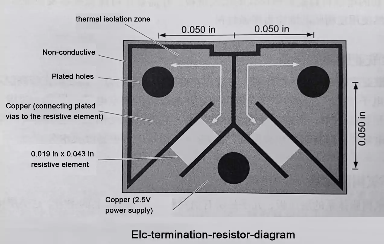
Created by plating a thin resistive layer (such as nickel alloy) onto copper foil, laminating it, and patterning it.
Typical sheet resistance: 25–100 Ω/sq
Typical usable resistance range: 10–1000 Ω
Applications include:
- transmission-line termination (ECL, high-speed digital)
- space-saving resistors in compact consumer devices (cameras, recorders, etc.)
These materials often involve proprietary processes and limited suppliers.
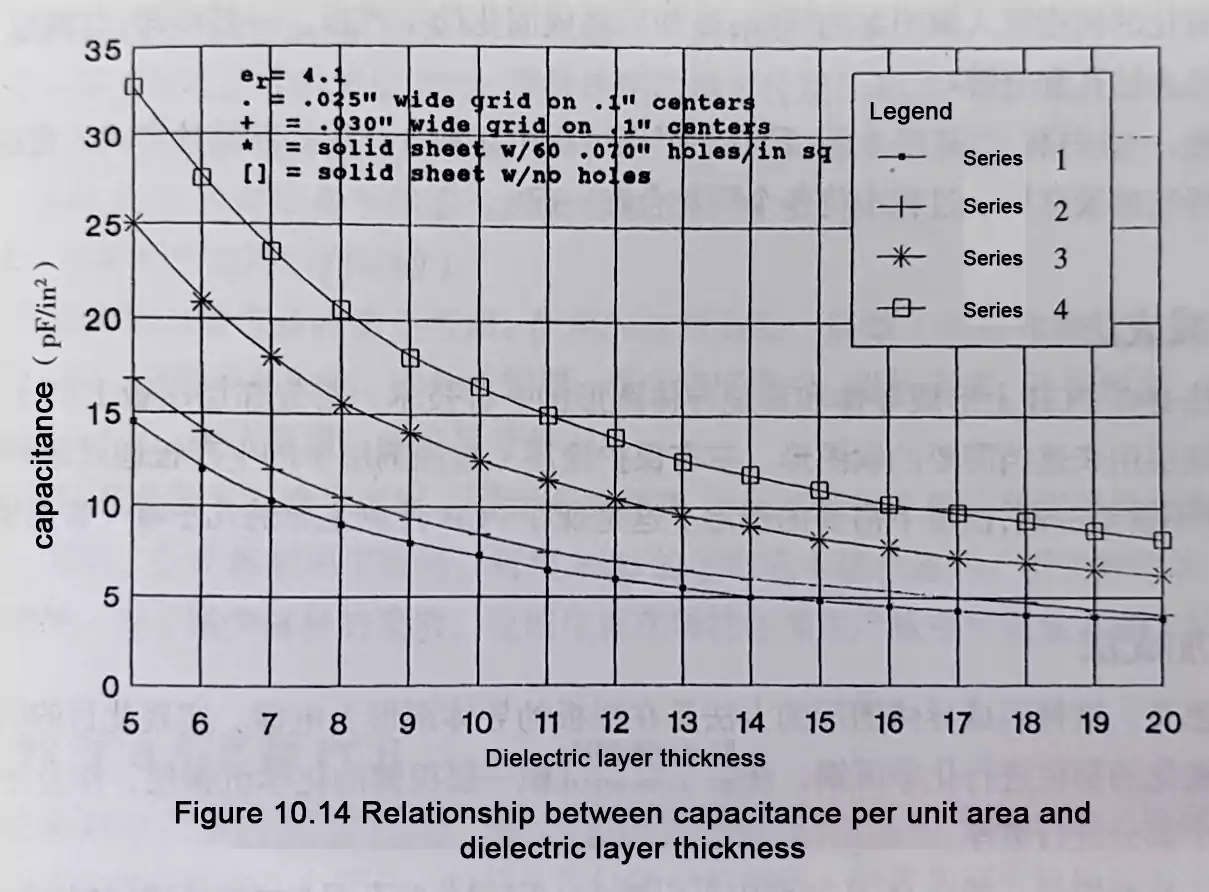
2. Embedded Capacitors
Formed by placing two copper planes extremely close together using an ultra-thin dielectric layer (0.4–2.0 mil).
Benefits:
- high-frequency decoupling
- extremely low ESL
- improved power-integrity performance
Primary drawback:
Requires additional layers → higher fabrication cost.
Used in high-speed CPU/FPGA boards, telecom backplanes, and premium high-performance systems.
Practical PCB board material Selection Tips for Engineers
To apply all this information effectively:
1. Start from system requirements—not habit
Don’t default to “just use FR-4.”
Consider speed, temperature, environment, voltage, lifetime, and reflow cycles.
2. For thick or high-layer PCBs, prioritize Tg + Z-axis CTE
This directly impacts hole reliability.
3. For high-speed or RF designs, Dk and Df matter most
Request frequency-dependent charts from your PCB manufacturer.
4. For high-humidity or outdoor applications, check WA and DBV
And coordinate PCB material choice with coating/encapsulation.
Conclusion
If you need support selecting the right PCB board material or optimizing your laminate stackup for high-speed, RF, or high-reliability applications, our team can help. FastTurnPCB provides professional PCB fabrication and assembly services with a strong focus on material performance, manufacturing consistency, and fast turnaround.
