

Rigid-flex PCB through-hole reliability starts with placement, interface control, and process compatibility.
The most reliable designs keep plated through-holes out of bend areas, reduce stress at pad transitions, and use hole-wall preparation methods that do not damage adhesive-related interfaces. In rigid-flex structures, reliability is shaped by both design and fabrication, not solely by copper plating.
That is why through-hole performance depends on more than metallization. Rigid-flex PCB desmear method, plasma etching, positive etchback, hole wall copper thickness, and material selection all influence whether a plated through hole will survive drilling, lamination, assembly, and long-term service.
Quick Answer
To improve rigid-flex PCB through-hole reliability, focus on these four fundamentals first:
- Bake before drilling and before plasma treatment to reduce moisture-related instability.
- Do not treat rigid-flex PCB desmear like a standard rigid-board desmear process.
- Use plasma etching for rigid-flex PCB structures when adhesive compatibility makes chemical desmear risky.
- Set the hole wall copper thickness according to the application class, not a universal rule
Why Through-Hole Reliability Is More Difficult in Rigid-Flex PCBs
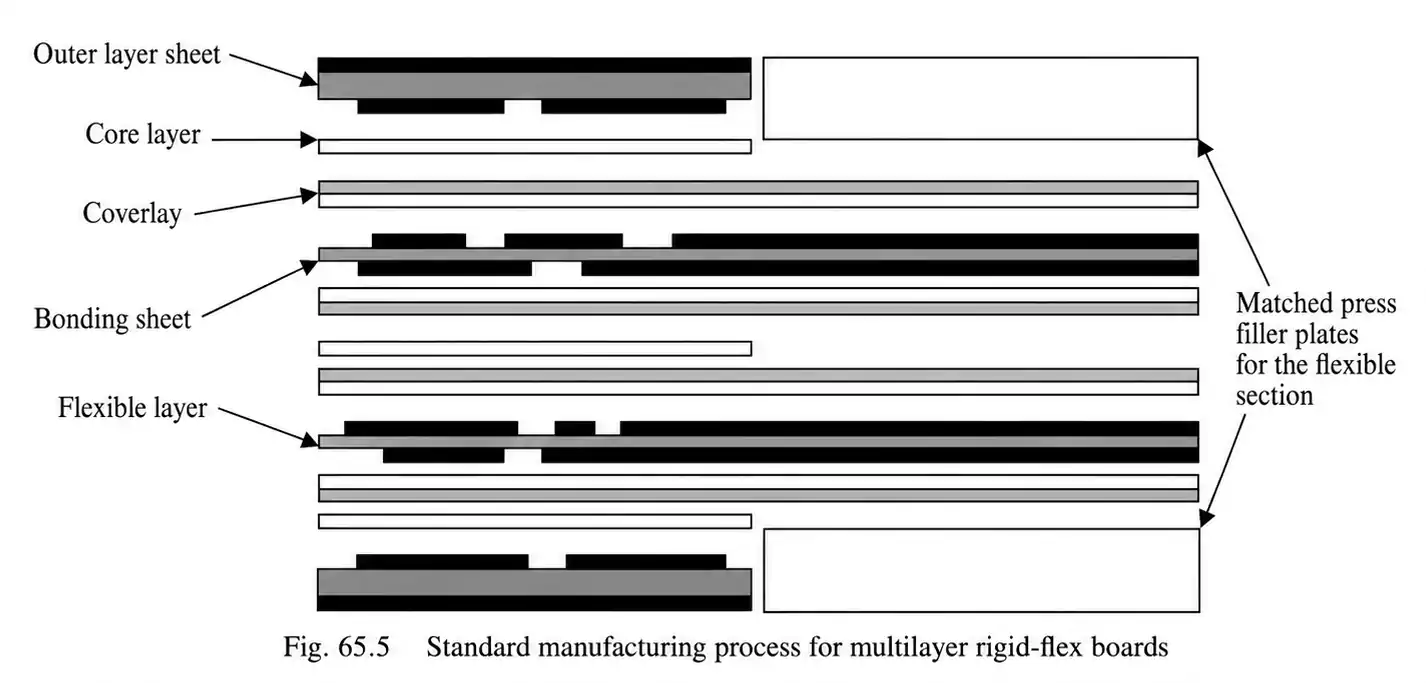
A rigid-flex PCB is not simply a rigid board with a flex section attached. It is an integrated structure that includes rigid areas, flexible areas, polyimide materials, adhesive systems, coverlay, and more complex lamination behavior.
That means the whole wall exists in a more sensitive material environment than it does in a conventional multilayer rigid board.
When a rigid-flex PCB with plated-through holes is built into flex-related layers, the process flow may resemble standard rigid-board inner-layer processing, but the drilling and preparation parameters cannot be copied directly. Drill conditions must be selected based on the actual stackup, material system, and reliability target.
Why the Process Window Is Narrower
Several factors make rigid-flex PCB through-hole reliability more sensitive than standard rigid-board reliability:
- Different materials expand differently under heat.
- Adhesive layers may respond poorly to aggressive chemical desmear
- Moisture has a stronger effect on hole-wall stability.
- Interface preparation matters as much as copper plating.
- Acceptable process margins are often narrower than in rigid boards.
Main Factors That Affect Rigid-Flex PCB Through-Hole Reliability
| Prebake | Reduces trapped moisture before drilling and plasma treatment |
| Rigid-flex PCB desmear method | Affects resin removal and adhesive stability |
| Plasma etching for rigid-flex PCB | Improves residue removal while protecting adhesive-related interfaces |
| Positive etchback | Improves hole-wall condition before metallization |
| Hole wall copper thickness | Must match the reliability level of the final product |
| Material selection | Defines the overall process window |
These decisions are connected. In rigid-flex manufacturing, none of them should be treated in isolation.
Reliability Starts Before Drilling
One of the most underestimated parts of rigid-flex fabrication is prebaking.
Before drilling, moisture should be reduced as much as possible. Before plasma treatment, moisture should be reduced again if needed. In practical terms, prebake is not just a preparation step. It is part of the whole-wall reliability strategy.
Why Prebake Matters
Prebaking helps:
- Reduce trapped moisture in polyimide and adhesive systems.
- Lower the risk of unstable hole-wall surfaces.
- Improve drilling consistency
- Stabilize the surface before desmearing the rigid-flex PCB and plasma treatment.
If moisture remains in the structure, the hole wall becomes harder to process consistently. That affects desmear, plasma treatment, and the final plated-through-hole reliability.
Rigid-Flex PCB Desmear Is Where the Process Really Changes
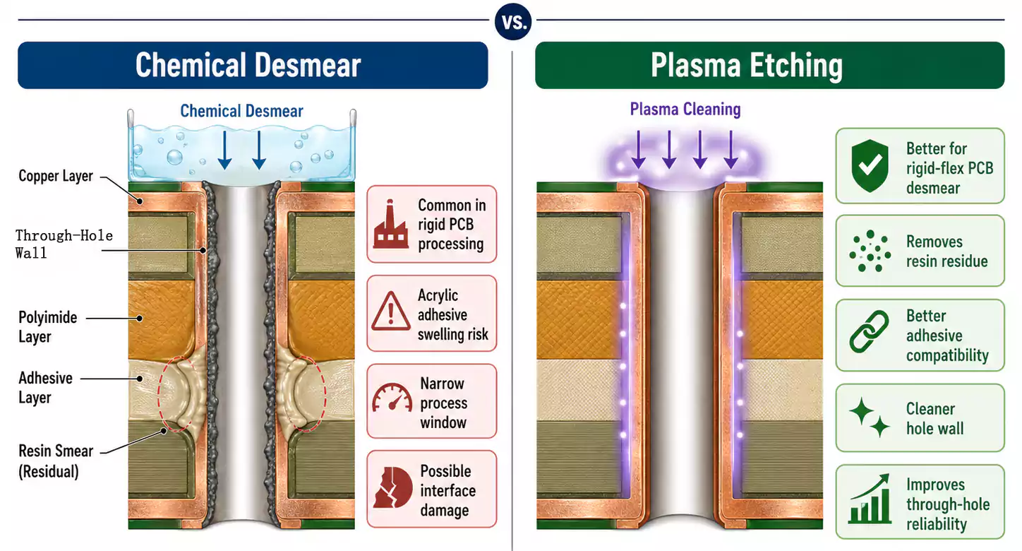
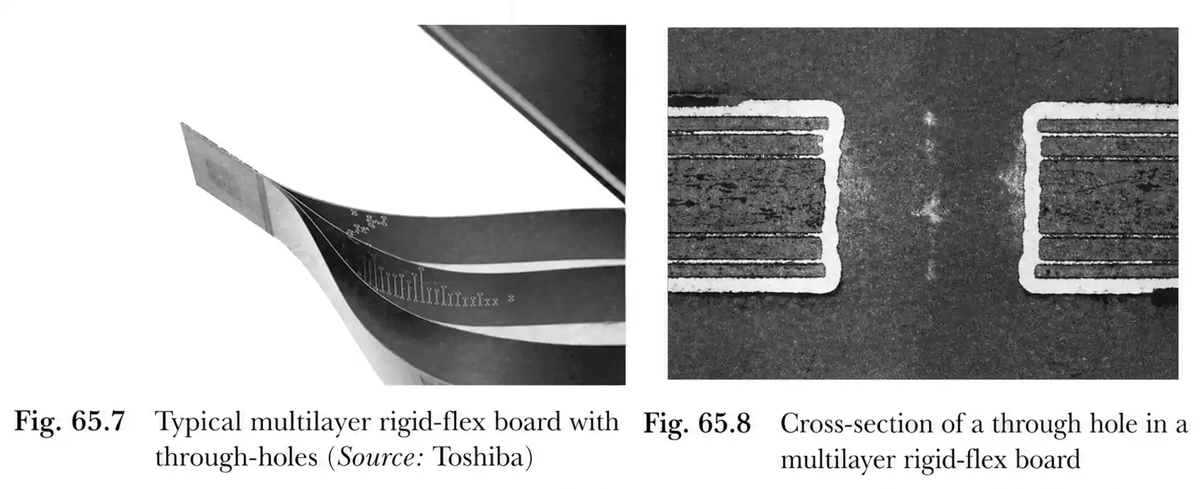
After lamination, a rigid-flex board can enter a plated-through-hole process flow that resembles multilayer rigid PCB fabrication. The major difference is desmear.
This is where many rigid-flex reliability problems begin.
In standard rigid boards, potassium permanganate desmear is common. In rigid-flex boards, that method can become risky, especially when acrylic adhesive systems are present. Acrylic adhesives may swell during chemical desmear, thereby weakening the hole-wall interface. If the chemical exposure window becomes too long, part of the adhesive layer may begin to break down.
Why Rigid-Flex PCB Desmear Needs a Different Approach
The challenge is not just removing the smear from the whole wall.
The challenge is removing the smear without damaging the interface on which the plated copper depends for long-term reliability.
That is why rigid-flex PCB desmear must be treated as a material-sensitive process rather than a standard rigid-board cleanup step.
Why Plasma Etching for Rigid-Flex PCB Structures Is Often the Better Option
For many builds, plasma etching for rigid-flex PCB fabrication is the safer and more reliable choice.
Instead of relying solely on aggressive chemical desmear, plasma etching can remove resin residue from the hole wall while being more compatible with adhesive-containing structures. That makes it especially useful in boards where polyimide, adhesive layers, and flex-related materials all affect the plated through-hole interface.
Advantages of Plasma Etching for Rigid-Flex PCB Builds
- Removes resin residue from the hole wall
- Offers better compatibility with adhesive-containing stackups
- Helps preserve the interface required for reliable metallization
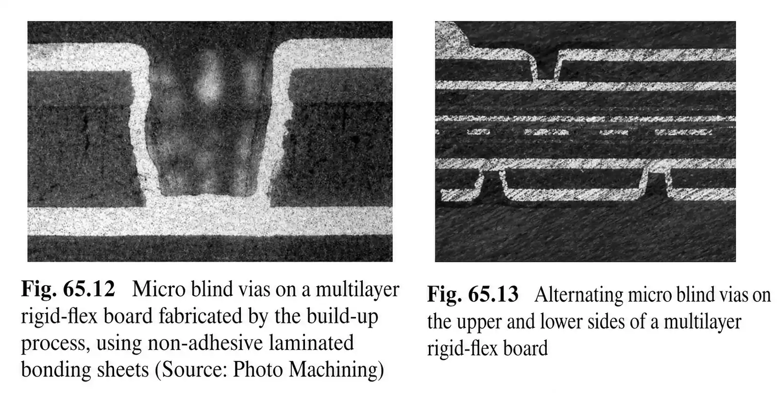
- Can also improve blind-via preparation in high-density rigid-flex designs
This is one of the most important reasons plasma etching for rigid-flex PCB structures is widely preferred over standard chemical desmear in demanding applications.
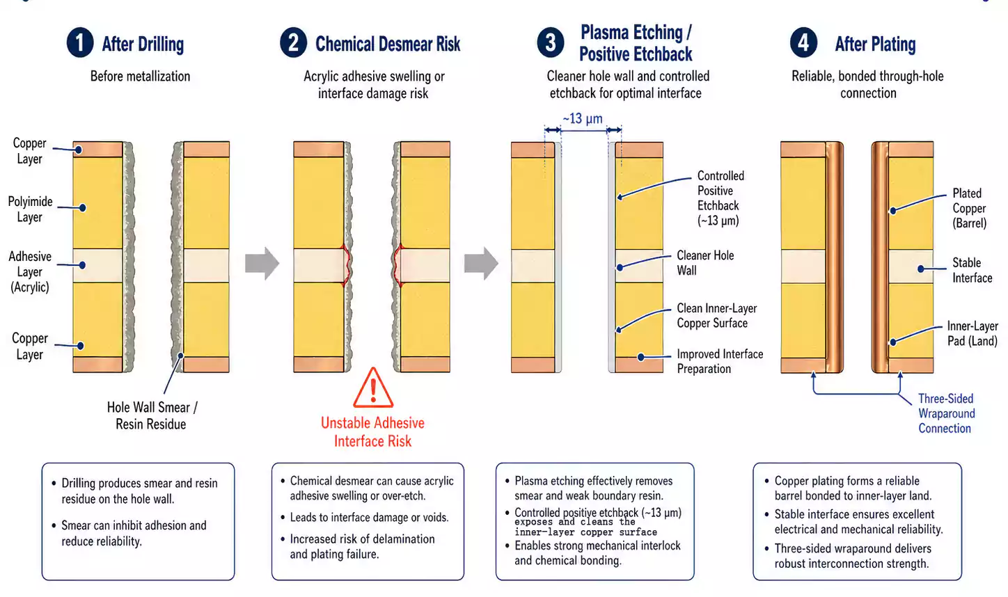
Positive Etchback: Why the 13 µm Guideline Matters
Plasma treatment can also create positive etchback. This is not simply extra material removal. It is a controlled way to improve the hole-wall interface quality before plating.
A positive etchback depth of around 13 µm is often considered a useful engineering reference point for high-reliability plated-through-hole processing.
What Positive Etchback Does
- Further conditions for the adhesive and polyimide layers
- Does not attack the metal layer
- Cleans the metal surface
- Helps create a stronger plated-copper-to-inner-layer interface
- Supports a more reliable wraparound copper connection at the inner-layer land
This is why rigid-flex PCB through-hole reliability cannot be reduced to copper thickness alone. Surface condition and interface geometry matter just as much.
Hole Wall Copper Thickness Must Match the Product Class
Hole wall copper thickness should never be selected in isolation. It must match the required reliability level of the end product.
Typical Hole Wall Copper Thickness Direction
| Aerospace / industrial high reliability | Typically greater than 25 µm |
| Certain IPC-related high-reliability conditions | Can exceed 35 µm |
| Consumer electronics | Can be below 15 µm if reliability is still maintained |
A rigid-flex PCB with plated-through holes used in aerospace, industrial controls, or medical electronics is expected to survive a very different operating environment than that of a thin, cost-sensitive consumer device.
Key Takeaway on Hole Wall Copper Thickness
- High-reliability products often use heavier copper to increase service margin.
- Consumer products may accept thinner copper to reduce thickness and cost.
- Neither choice is universally right or wrong.
- The correct target depends on the application, not just the board category.
Material Selection Shapes the Entire Process Window
Rigid-flex PCB through-hole reliability begins with material choice.
In higher-reliability applications, thicker polyimide films are often preferred because they provide better dimensional stability and durability during fabrication. Consumer electronics often move toward thinner dielectric materials to support smaller, lighter assemblies.
Adhesive chemistry also changes the process window.
| Acrylic adhesive | Stronger bond strength | Lower heat resistance, higher shrinkage, more desmear sensitivity |
| Epoxy adhesive | Better heat resistance | Longer cure time, somewhat lower bond strength |
| Adhesiveless copper-clad material | Better thermal stability, lower expansion, thinner final build | May require tighter process control |
Adhesiveless materials are especially useful in high-density or high-reliability rigid-flex builds because they can improve thermal stability and reduce desmear-related risk.
Heat-bondable polyimide coverlays and bonding sheets can also reduce drill smear, although they generally require higher processing temperatures and tighter manufacturing control.
Plating Parameters Should Be Set by Reliability Data
Once drilling, prebake, rigid-flex PCB desmear, and plasma treatment are complete, the hole can move into a more conventional plating sequence.
But that does not mean the plating window should be copied from a standard rigid-board job.
The more reliable approach is to set plating conditions based on actual through-hole reliability test data. Material choice, desmear method, interface condition, and etchback all affect how well the plated copper will perform.
Best Practice
- Do not assume one plating window fits every rigid-flex stackup
- Validate plating against the actual material system.
- Treat plating as the final step in a controlled chain, not the first place to solve reliability problems
High-Density Rigid-Flex Makes Through-Hole Reliability Even More Sensitive
As rigid-flex designs move into higher-density applications, the process margin becomes tighter.
Industrial and medical rigid-flex PCB constructions may include:
- Line spacing below 100 µm
- Hole diameters below 100 µm
- Thin adhesiveless copper-clad polyimide
- Laser-drilled microvias or blind vias
- Thin copper combined with high reliability expectations
In these structures, residue removal, plasma treatment, and interface preparation matter even more because the features are smaller and less forgiving.
That means rigid-flex PCB through-hole reliability does not become less important in HDI-style designs. It becomes more delicate.
A Simple Process View
A practical way to think about rigid-flex PCB plated through-hole reliability is as a sequence:
- Choose a material system that fits the reliability target.
- Prebake to reduce moisture before drilling.
- Drill with parameters suited to the real stackup
- Use a rigid-flex PCB desmear method that will not damage the adhesive system.
- Apply plasma etching and controlled positive etchback when needed.
- Plate to a hole wall copper thickness appropriate for the application class
- Confirm the plating window with reliability data.
Common Mistakes to Avoid
Some of the most common causes of poor rigid-flex PCB through-hole reliability include:
- Treating rigid-flex PCB desmear like a standard rigid-board process
- Ignoring acrylic adhesive swelling during chemical desmear
- Skipping or minimizing prebake
- Assuming a thicker hole wall copper thickness automatically guarantees better reliability
- Reusing plating parameters from unrelated builds
- Chasing density without giving enough attention to the hole-wall interface preparation
FAQ
Why is plasma etching preferred in many rigid-flex PCB desmear processes?
Plasma etching can remove hole-wall residue while being gentler on adhesive-related materials. That makes it better suited to many rigid-flex structures than aggressive chemical desmear alone.
Why is prebake important for rigid-flex PCB through-hole reliability?
Because moisture can destabilize the hole-wall interface and reduce process consistency. Prebake helps create a more controlled surface before drilling, desmear, and metallization.
What does the 13 µm positive etchback guideline mean?
It is a practical engineering reference for controlled hole-wall conditioning. The goal is to improve the metallization interface, not simply to etch more aggressively.
Is a thicker-walled copper hole always better?
No. Thicker copper is often preferred in high-reliability products, but thinner copper may still be appropriate in consumer electronics when thickness and cost are tightly constrained. The correct value depends on the application.
Final Takeaway
Reliable through-holes in rigid-flex PCBs are built through process control, not by optimizing one step in isolation.
Prebake, desmear, plasma treatment, etchback, material compatibility, and copper thickness all shape the final interconnect. When those factors are aligned, plated through-holes are far more likely to withstand fabrication, assembly, and long-term use.
At FastTurn PCB, rigid-flex manufacturing is approached with that full-process mindset, because lasting board performance depends on interconnects that stay stable in real-world conditions.
