Rigid-Flex PCB Manufacturer

Custom Rigid-Flex PCB Fabrication & Supply

As a premier rigid-flex PCB manufacturer and supplier in China, we provide robust rigid-flex pcb fabrication with seamless integration of rigid and flexible layers. From prototype to high-volume runs, upload your Gerber files now for a fast, competitive quote.

What is a Rigid-Flex PCB?

Rigid Flex PCBs

Rigid-Flex PCBs combine the best of both rigid and flexible circuit technologies into a single, unified board. This hybrid structure allows for complex three-dimensional designs, enabling electronic components to be mounted on both rigid sections while flexible layers provide interconnectivity across dynamic or confined spaces.

Unlike traditional rigid boards that require connectors or cables for interconnection, Rigid-Flex PCBs streamline the overall design by eliminating these components—resulting in improved reliability, reduced weight, and enhanced signal integrity.

These boards are widely used in mission-critical and compact applications such as medical devices, aerospace systems, military equipment, cameras, and wearables, where high mechanical reliability, space savings, and resistance to vibration and bending are essential.

Why Choose Us

End-to-End Manufacturing Expertise

We specialize in full-cycle rigid-flex PCB production—from prototyping to mass production. Our in-house facilities are equipped with advanced processing lines tailored for complex rigid-flex structures, ensuring tight process control and consistent quality.

Engineering-Driven Support

Our experienced engineering team provides comprehensive DFM (Design for Manufacturability) analysis, helping customers optimize stack-up, impedance, and bend radius before fabrication begins. We support Gerber, ODB++, and IPC standards for seamless collaboration.

Certified Quality & Advanced Equipment

All of our manufacturing processes are ISO 9001, UL, and RoHS certified. With laser drilling, precision lamination, and AOI/X-ray inspection, we meet the high standards required for aerospace, military, and medical applications.

Fast Turnaround & Global Delivery

We offer expedited lead times for both prototypes and high-volume orders. With a flexible production model and global logistics network, we deliver to customers worldwide—on time, every time.

Responsive Customer Service

From quote to shipment, our dedicated support team provides 24/7 technical assistance and order tracking. Whether you’re a startup engineer or a Tier-1 OEM, we treat every project with precision and urgency.

Product Showcase

Capabilities

Capability Parameter
Layer 26L
26L 0.065 mm/0.065 mm
Min Hole/Pa Size 0.10/0.35 mm
Rigid-Flex Thickness 0.25-6.0mm
Drilling Accuracy +/-0.05 mm
PTH Diameter Tolerance +/-0.05 mm
Max Wpnl Size 620 mm x 500 mm
Finish Copper (Flex Part) 0.5-2oz
Finish Copper (Rigid Part) 1-4oz
Surface Treatment ENIG
Electric Gold
IM-Ag
Electric Ag
HASL
HASL-LF
IM-Sn
Electric Sn
OSP
Caborn
Pt
NI-Pd-AU
Max Board Thickness: PTH Diameter 13:01
Build Time 7-20 Days

Manufacturing Process

Material Preparation

NO.1

Select high-performance polyimide and FR4 laminates based on layer stackup and design.

Inner Layer Imaging & Etching

NO.2

Create fine copper traces using photolithography and precision chemical etching.

Lamination of Rigid and Flex Layers

NO.3

Bond rigid and flexible layers into a unified structure using heat, pressure, and alignment control.

Drilling & Copper Plating

NO.4

Drill microvias and through-holes, then plate with copper to form reliable interlayer connections.

Outer Layer Imaging & Patterning

NO.5

Define and etch the outer circuitry, ensuring signal integrity and trace accuracy.

Surface Finishing

NO.6

Apply finishes like ENIG, HASL, or OSP to protect pads and improve solderability.

Coverlay & Stiffener Application

NO.7

Add protective coverlays over flex zones and stiffeners under connectors or components.

Profiling & Final Testing

NO.8

Laser-cut or route board outlines, then perform 100% E-test and visual inspection.

Application Industries

Medical Devices

Medical Devices

Aerospace

Aerospace & Defense

Automotive Electronics

Automotive Electronics

Consumer Electronics

Consumer Electronics

Industrial Control Systems

Industrial Control Systems

Wearable Technology

Wearable Technology

Technical Support

Design for Manufacturability (DFM) Review

Every project receives a free DFM check before fabrication. We analyze your stack-up, trace width, bend radius, drill strategy, and impedance control to ensure your design is ready for production.

Stack-Up Optimization & Material Guidance

Our engineers assist with optimal material selection (PI, FR4, adhesiveless laminates), copper weights, and dielectric configurations based on your electrical and mechanical requirements.

Comprehensive File Support

We accept Gerber, ODB++, IPC-2581, and other mainstream formats. Our CAM team works closely with you to clarify build instructions, panelization needs, and stiffener placements.

Responsive Technical Communication

Get fast responses and expert feedback during the quoting, design, and production stages. We’re available via email, online chat, or phone to ensure your project moves forward smoothly.

FAQ

Rigid Flex PCBs are printed circuit boards that combine the characteristics of both rigid and flexible circuit boards.

 Their main advantage lies in providing higher design flexibility, allowing for complex interconnections to be achieved in a compact space while maintaining the stability of rigid regions and the bending ability of flexible regions.

 This helps to reduce the overall device size, improve reliability, and lower costs.

The manufacturing process of Rigid Flex PCBs involves multiple key steps, including material selection, design layout, laser drilling, electroplating, etching, lamination, folding and assembly of flexible areas, etc.

 Among them, the lamination step is particularly crucial because it requires precise bonding of rigid and flexible layers together while ensuring the reliability of interlayer connections.

 In addition, the folding of flexible areas also requires precise control to avoid cracking or damage during the bending process.

When designing Rigid Flex PCBs, multiple factors need to be considered, including the overall size of the circuit board, layout of rigid and flexible areas, signal integrity, thermal management, material selection, and stacking structure.

 Designers need to carefully plan signal paths to ensure efficient transmission of signals between rigid and flexible areas.

 Meanwhile, it is also necessary to consider the matching of coefficient of thermal expansion (CTE) to avoid excessive stress during temperature changes.

Rigid Flex PCBs are widely used in various fields, including smartphones, tablets, wearable devices, medical equipment, aerospace systems, and automotive electronics.

 They are particularly suitable for application scenarios that require high integration, compact design, and complex interconnection.

 In these fields, Rigid Flex PCBs can provide excellent performance and reliability while meeting the demand for miniaturization and lightweighting.

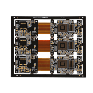
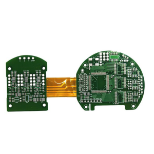
To ensure the quality and reliability of Rigid Flex PCBs, a series of measures need to be taken.

 Firstly, manufacturers need to select high-quality raw materials and ensure that every step of the manufacturing process meets strict process standards.

 Secondly, strict testing and inspection are required, including electrical performance testing, reliability testing, and environmental adaptability testing.

 In addition, designers also need to consider redundancy and fault tolerance mechanisms in their designs to improve the overall reliability and stability of the circuit board.

 Through these measures, it can be ensured that Rigid Flex PCBs perform well in their final application, meeting the needs and expectations of customers.

Put your parts
into production today

All information and uploads are secure and confidential.