

Introduction
As electronic devices get smaller, lighter, and smarter, engineers are constantly pushed to create more compact yet reliable hardware solutions. That’s where the rigid flex PCB comes in—a hybrid board design that combines rigid and flexible layers into one seamless structure.
Unlike traditional PCBs, rigid flex circuits allow parts of the board to bend and fold, making them perfect for tight enclosures and dynamic applications. From medical wearables to aerospace systems and foldable phones, these boards enable innovative layouts without sacrificing performance or durability.
In this article, we’ll break down everything you need to know about rigid flex PCBs—from how they work and where they’re used, to key design tips, manufacturing insights, and how to choose the right supplier for your next project.
What Is a Rigid‑Flex PCB?
A rigid‑flex PCB (rigid flex circuit) is a hybrid printed circuit board that combines rigid board sections and flexible circuit layers into a single integrated design. Instead of connecting a rigid PCB to a flexible cable using connectors or solder joints, a rigid‑flex PCB uses internal flexible layers to form continuous electrical interconnections between rigid sections. This structure allows part of the board to bend or fold while other sections remain stiff for component mounting and mechanical support.
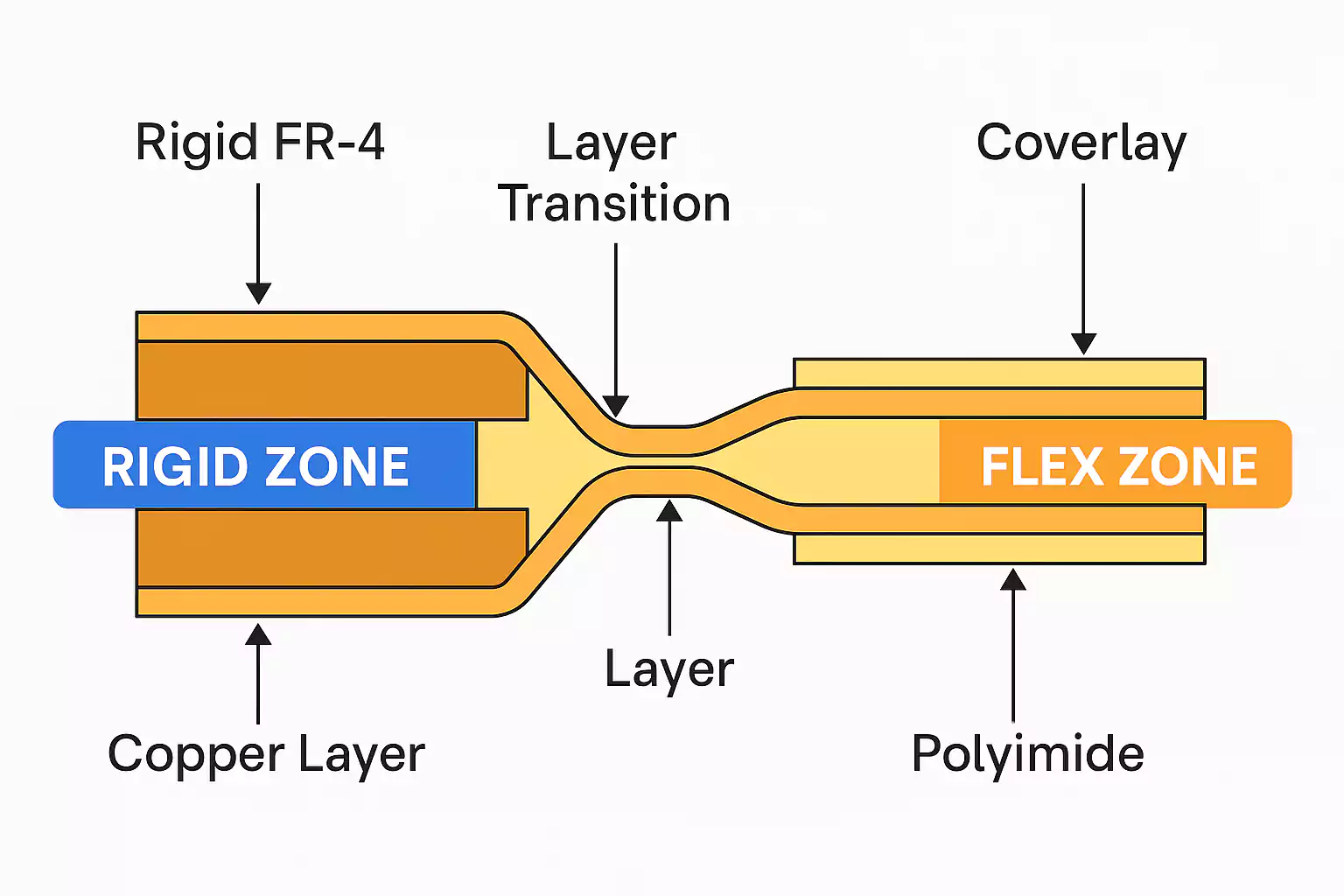
In most configurations, multiple layers of polyimide‑based flexible circuitry are laminated together with FR‑4 rigid layers, creating a unified stack‑up. The flex layers act as the internal wiring harness, enabling reliable high‑density routing between rigid zones without bulky connectors or wires. This reduces failure points and improves electrical performance—especially in environments where vibration, shock, or space constraints are critical factors.
Typical rigid‑flex PCB structures include:
- Rigid‑in‑Flex designs with flex layers inside the rigid stack‑up
- Bookbinder‑style flex for repeated bending applications
- Multi‑layer rigid with multi‑layer flex for complex electronics
Key Benefits of Rigid-Flex PCBs
Rigid flex PCBs offer a unique combination of mechanical strength and design flexibility, making them an ideal choice for compact, high-performance electronic systems. Here are some of the core advantages that set them apart from traditional rigid or flexible boards:
1. Space and Weight Savings
Because rigid flex PCBs eliminate the need for bulky connectors, cables, and separate board assemblies, they significantly reduce the size and weight of the final product. This is especially important in applications like wearable tech, aerospace, and medical devices,where space is limited and every gram counts.
2. Improved Reliability
By integrating rigid and flexible sections into a single board, the need for solder joints and connectors between multiple PCBs is reduced—minimizing potential failure points. This improves the overall durability and performance of the device, especially in high-vibration or mobile environments.
3. Enhanced Design Flexibility
Rigid flex circuits can bend, fold, or twist into compact enclosures without compromising the structural integrity of the system. This allows for 3D packaging designs and more innovative product layouts that are not possible with standard PCBs.
4. Better Signal Integrity
With fewer interconnects and a streamlined layout, signal paths are shorter and more stable. This improves impedance control and reduces the risk of electromagnetic interference (EMI), which is critical in high-speed and high-frequency applications.
5. Cost Savings in Complex Designs
While the initial fabrication cost of a rigid flex PCB may be higher than a standard board, the reduction in connectors, cables, and assembly time can lead to long-term cost savings—particularly in complex or high-density assemblies.
Design Considerations for Rigid-Flex PCBs
Designing a rigid flex PCB is more complex than designing a standard rigid or flexible board. These hybrid circuits must address both mechanical reliability and electrical performance across different material zones. Here are the key design considerations to ensure long-term durability and functional success:
1. Bend Radius Matters
One of the most critical factors in rigid flex design is the bend radius of the flexible section. If the bend radius is too tight, it can lead to copper cracking, delamination, or signal distortion. As a general rule:
- Static bend (fold once): minimum bend radius should be 6× the flex thickness.
- Dynamic bend (flex repeatedly): minimum bend radius should be 12–15× the flex thickness.
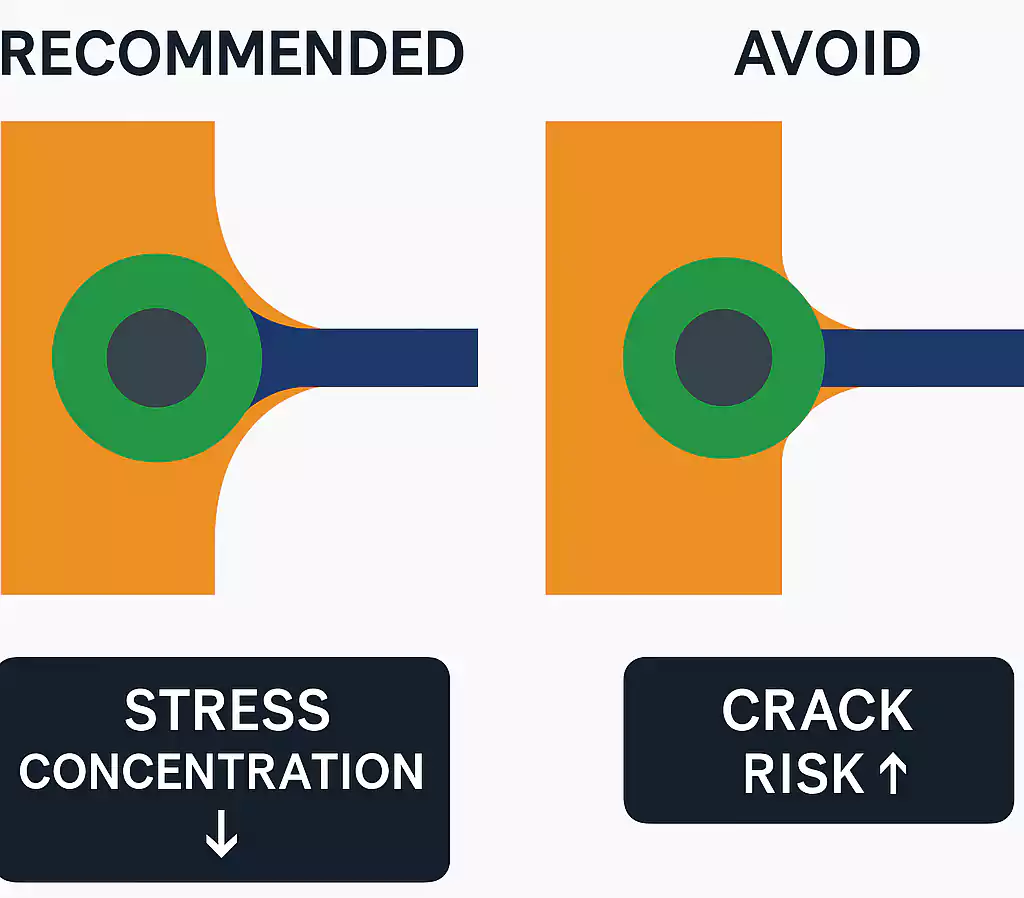
2. Use Teardrop Pads at Via Transitions
Teardrop pads help strengthen the transition between traces and vias or through-holes. In flexible sections, they reduce mechanical stress and improve drill alignment accuracy—especially during repeated bending or vibration.
3. Signal Integrity and EMI Control
Maintaining signal integrity in the flex section can be challenging due to the close proximity of copper traces and the flexible material’s movement. To reduce EMI and crosstalk:
- Avoid routing high-speed signals across the bend zone.
- Maintain proper spacing between signal lines.
- Add ground shielding in critical areas when possible.
4. Rounded Corner Design
Sharp 90° corners can cause mechanical stress and cracking in flexible areas. Always use rounded corners (minimum radius of 1.5 mm is recommended) to reduce tear risks and enhance the board’s bending reliability.
5. Smooth Layer Transitions
Ensure clean and gradual transitions between the rigid and flex sections. Misaligned or abrupt changes in stack-up can result in impedance mismatches and signal degradation. Use gradual tapering and avoid sudden shifts in trace width or plane areas.
6. Stack-Up Symmetry & Flex Layer Balance
An unbalanced stack-up may cause warping or twisting, especially after reflow. Always design symmetrical copper layers and consistent dielectric thicknesses on both sides of the flex region.
Manufacturing Challenges of Rigid-Flex PCBs
Key challenges include:
- Material Compatibility
Different thermal expansion rates between FR-4 and polyimide require careful material selection to avoid delamination. - Layer Lamination
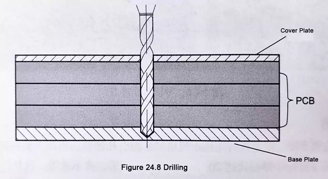
Multiple lamination cycles are needed to bond rigid and flex layers. Precise alignment and adhesive control are essential. - Drilling and Plating
Vias must pass through both rigid and flex areas. Any misalignment or plating defect can compromise electrical reliability. - Flex Area Handling
Flexible substrates are delicate and prone to damage. Clean environments and soft tooling are necessary during processing. - Testing and Quality Control
Rigid flex circuits are often used in critical applications and must meet IPC Class 3 standards for durability and performance
Typical Applications of Rigid-Flex PCBs
Rigid flex PCBs are widely used in industries that demand compact design, high reliability, and mechanical durability.
- Medical Devices
Ideal for compact and reliable designs in wearable monitors, imaging equipment, and implantable devices. - Consumer Electronics
Used in smartphones, smartwatches, and foldable devices for 3D integration and space efficiency. - Automotive Electronics
Suitable for ADAS, cameras, and infotainment systems where vibration resistance and long-term reliability are critical. - Aerospace & Defense
Applied in aircraft systems, satellites, and military-grade communication devices due to their strength and lightweight structure. - Industrial Applications
Enables robust connections in robotics, control units, and automation systems operating under continuous movement or stress.
Rigid flex circuits offer a flexible solution where traditional PCBs fall short, making them essential in modern electronic product design.
Rigid-Flex vs Rigid or Flex PCB Comparison Table
| PCB Type | Structure | Typical Applications | Advantages | Limitations |
|---|---|---|---|---|
| Rigid PCB | Solid fiberglass (FR4) board | Consumer electronics, computers, appliances | Low cost, easy to manufacture, mechanically strong | No flexibility, not suitable for compact 3D designs |
| Flex PCB | Fully flexible polyimide-based substrate | Cameras, wearables, medical sensors, mobile tech | Lightweight, bendable, fits in tight spaces | Delicate, more complex assembly, higher material cost |
| Rigid-Flex PCB | Integrated rigid and flexible layers | Aerospace, military, foldables, implants, drones | Combines strengths of rigid and flex, fewer connectors, better reliability, supports 3D layouts | Higher cost, complex design and fabrication process |
Conclusion
Rigid flex PCBs provide a reliable and space-saving solution for complex electronic designs. By combining rigid and flexible layers, they support advanced functionality in compact formats, making them ideal for industries like medical, aerospace, and consumer electronics.

To fully realize the benefits of rigid flex PCBs, careful design and collaboration with an experienced manufacturer are essential. At Fast Turn PCB, we offer end-to-end support—from prototype to production—to help you bring your designs to life with precision and speed.
Contact us today to request a quote or get a free design consultation.