Introduction
Surface-mount technology (SMT) assembly—often called SMT PCB assembly or surface-mount PCB assembly—has become the foundation of modern electronics manufacturing.
By placing miniature surface-mount devices (SMDs) directly onto copper pads, SMT enables lighter, faster and more reliable circuits than the through-hole methods of the past. From smartphones and wearables to industrial automation and EV power systems, virtually every high-density product you hold today relies on precise PCB SMT assembly techniques.
Yet "doing SMT right" involves far more than simply running boards through a pick-and-place machine. Successful projects demand a clear grasp of designfor-assembly rules, stencil and paste selection, reflow profiling, inline inspection and cost trade-offs—all before the first component is placed.
That's why this deep-dive guide distills the entire SMT workflow into practical, engineering-level insights you can act on immediately.
SMT Assembly Essentials
1. What Is SMT Assembly?
Surface-mount technology (SMT) assembly is the process of mounting tiny surface-mount devices (SMDs) directly onto a printed-circuit board's copper pads, eliminating the need for drilled holes. Because components sit flat against the board, an SMT PCB assembly packs more functionality into less space and supports automated, high-speed production lines.
| Term | Meaning | Where It Fits |
|---|---|---|
| SMD (Surface-Mount Device) | The individual component (resistor, IC, BGA, etc.) that is placed | Building block |
| SMT (Surface-Mount Technology) | The overall manufacturing methodology—including solder paste printing, pick-and-place, reflow and inspection | The "how" |
| SMT Assembly / Surface-Mount PCB Assembly | The completed board populated solely (or mainly) with SMDs | The finished product |
| THT (Through-Hole Technology) | Legacy method where leads pass through drilled holes and are wave-soldered | Often used for connectors, large passives or high-stress parts |
2. A 60-Second Timeline of SMT
- 1960s – Early Trials: IBM experiments with "planar mounting" to shrink military circuits.
- 1980 – First Mass Adoption: Consumer VCRs and pagers embrace 1206/0805 packages, cutting board area by ~50 %.
- 1990s – Mobile Boom: 0603/0402 passives support the first flip phones; BGA and CSP packages push I/O density.
- 2005–2015 – Miniaturization Race: 0201, then 01005 chip sizes enable smartphones and wearables; reflow ovens add nitrogen capability to control voiding.
- Today: 0.3 mm-pitch BGAs, embedded passives and automated optical/X-ray AI inspection drive defect rates below 50 DPMO on high-volume PCB SMT assembly lines.
3. Why Choose SMT Over THT?
| Factor | SMT Assembly | Through-Hole Assembly |
|---|---|---|
| Component Density | 2–10 × higher; both sides usable | Limited by hole diameter & spacing |
| Electrical Performance | Lower parasitics → higher signal integrity | Longer lead lengths add inductance |
| Automation Speed | >60 000 CPH* on modern placers | 3 000–4 000 CPH with wave-solder pallets |
| Thermal & Mechanical Stress | Smaller thermal mass; good shock resistance | Leads absorb stress but add mass |
| Cost at Volume | ↓ Board size + full automation = lower BOM & labor | ↑ Drilling, manual insertion, wave solder costs |
*CPH = components per hour.
Combining both techniques—called mixed or hybrid assembly—remains common for large connectors, transformers or heat-sinking parts that exceed SMT's mechanical limits.
4. Inside an SMT Line (The 5 Critical Stations)
- Stencil Printing – deposits solder paste ± 25 µm accuracy.
- Solder Paste Inspection (SPI) – 3-D scans paste height/volume.
- Pick-and-Place – vision-guided robots place SMDs at up to 4 m/s.
- Reflow Oven – multi-zone thermal profile melts paste and forms joints.
- Post-Reflow Inspection – AOI, X-ray and (for high-reliability) ICT catch opens, bridges and voids.
Understanding these stations early helps designers apply proper pad geometries, fiducials and panelization rules, preventing costly respins later.
SMT vs THT vs Mixed Assembly
Selecting the right assembly method is a balancing act between size, reliability, cost and production speed. The matrix below distills the most common decision factors engineers weigh when choosing surface-mount technology (SMT), through-hole technology (THT) or a mixed (hybrid) PCB assembly strategy.
| Criterion | SMT Assembly | THT Assembly | Mixed Assembly |
|---|---|---|---|
| Component Density | Highest—both sides usable; parts down to 01005 and 0.3 mm BGA pitch | Lowest—hole diameter & keep-out zones limit routing | Medium—SMT for small parts, THT for bulky/high-stress parts |
| Electrical Performance | Shorter interconnects → lower inductance/ capacitance; ideal for RF & high-speed | Longer leads add parasitics; signal integrity harder above 100 MHz | Critical nets SMT; power/connector nets THT |
| Mechanical Strength | Good for shock & vibration if board is well supported | Leads anchor parts through the board—best for pull/torque loads | Strategically uses THT where strain relief is needed |
| Assembly Speed | > 60k CPH on modern pick-and-place; fully automated reflow | 3 k–4 k CPH; often manual insertion + wave or selective solder | Two passes (reflow + wave/selective) extend cycle time |
| Tooling / NPI Cost | Low—no drilling for component leads; stencils inexpensive | Higher—drilling & wave pallets; hand-load labor | Highest initial setup; two soldering profiles, two inspection flows |
| Board Real-Estate / Layer Count | Smaller boards or fewer layers → lower bare-board cost | Larger boards; extra layers (for power or routing) common | Board size reduction vs pure THT, but less compact than all-SMT |
| Inspection & Test | Automated AOI, SPI, X-ray, ICT with pogo pins | Manual visual + ICT; AOI for wave solder less common | Dual inspection: AOI after reflow; wave solder joints manual or AOI-THT |
| Thermal Cycling Reliability | Good when reflow profile optimized; small mass reduces ΔT stress | Excellent—leads act as stress relief during expansion | Depends on joint type; verify reflow + wave compatibility |
| Typical Applications | Smartphones, IoT modules, wearables, high-frequency RF boards | Power supplies, automotive connectors, industrial relays, aerospace | Consumer appliances, LED lighting, EV chargers, medical devices |
| Cleanliness / Contamination Risk | Requires controlled reflow atmosphere; no-clean pastes common | Flux residues from wave solder often require wash | Must match chemistries—no-clean reflow + washable wave flux |
Key Insights for Design & Manufacturing Teams
1. Optimize for Density First
If product size, weight or RF integrity are top priorities, default to a fully SMT PCB assembly. You'll minimize layer count, shorten trace lengths and open the door to volume automation.
2. Leverage THT Where Abuse Is Inevitable
High-current connectors, transformers, large electrolytics and mechanical switches handle torque, heat rise and plug cycles far better with through-hole anchoring.
3. Plan Early for Hybrid Costs
A mixed assembly saves board real estate but adds tooling (wave pallets, selective solder nozzles) and a second inspection flow. Model these extra steps in your cost-of-ownership spreadsheet to avoid surprises.
4. Synchronize Thermal Profiles
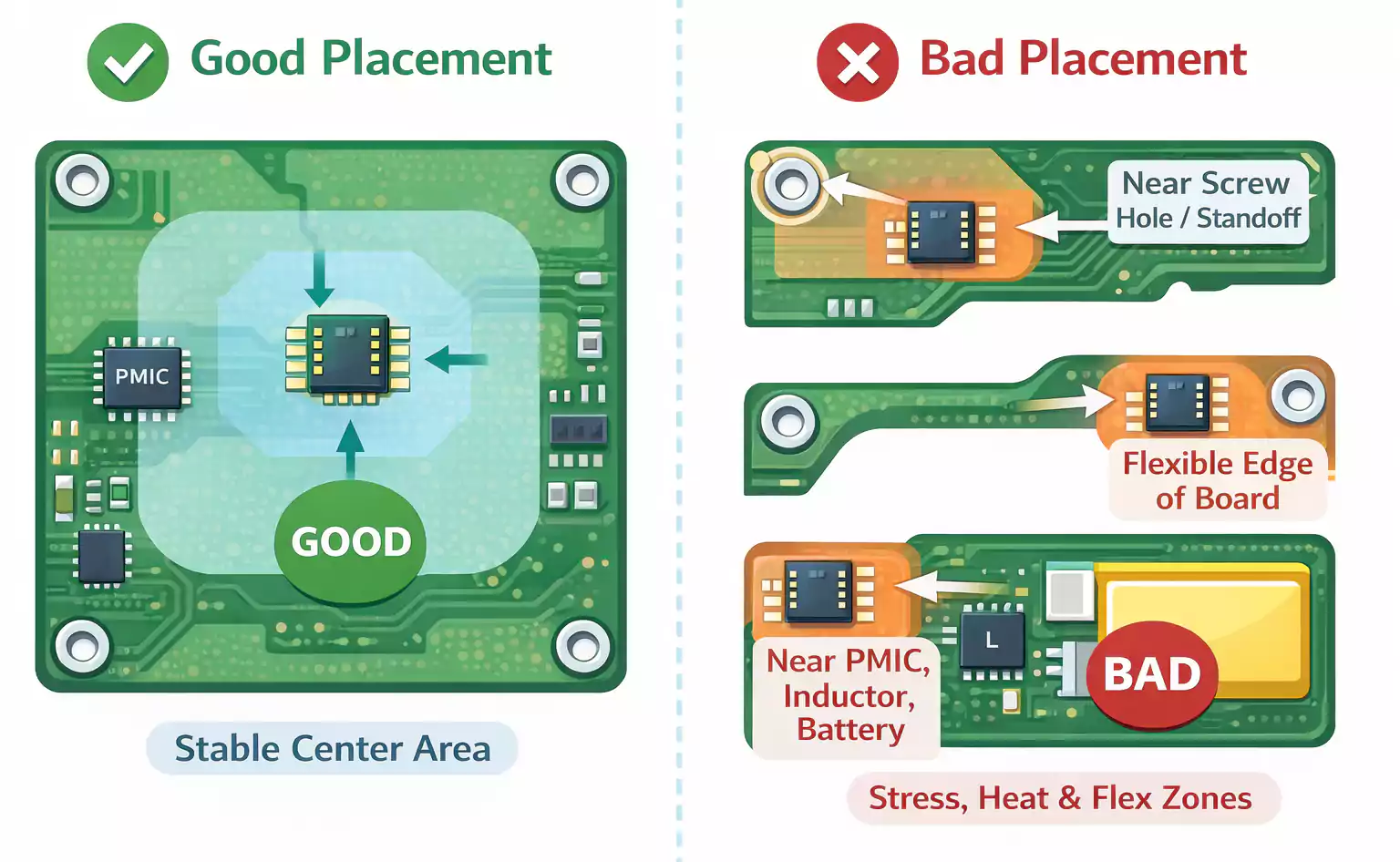
Combining reflow (for SMT) and wave/selective solder (for THT) requires ensuring THT components can survive the reflow peak (typically 245 °C) and that SMT parts aren't scorched by wave dwell. Place your temperature-sensitive modules accordingly.
Document Assembly Intent in the BOM
Call out which reference designators are SMT, THT or optional "either-or." Clear fabrication notes reduce NPI spin time and prevent shop-floor ambiguity.
The SMT Assembly Process—8 Steps Explained in Detail
A modern SMT assembly line is a tightly choreographed sequence of machines, sensors and feedback loops that can place up to 60 000 components per hour while holding defect rates below a few parts per million.
Mastering the eight steps below will help you design boards that flow through production "first time-right," slash NPI spin cycles and hit aggressive cost targets.
Step 1 – Stencil Printing: Depositing Solder Paste
- Goal: Print a precisely metered volume of solder paste on each pad, ±25 µm in X-Y and ±15 % in height.
- Key variables: stencil thickness (typically 100–150 µm), aperture shape (home-plate, window-pane, stepped), squeegee speed/pressure and paste chemistry (Sn-Ag-Cu, low-temperature Bi-Sn).
- Best practice: Use laser-cut, nano-coated stainless stencils to reduce paste adhesion and minimize bridging on fine-pitch BGAs.
- Common defects: insufficient paste → opens; excess paste → shorts/voids; clogged apertures → tombstoning. Inline SPI coverage at this stage detects >80% of downstream defects.
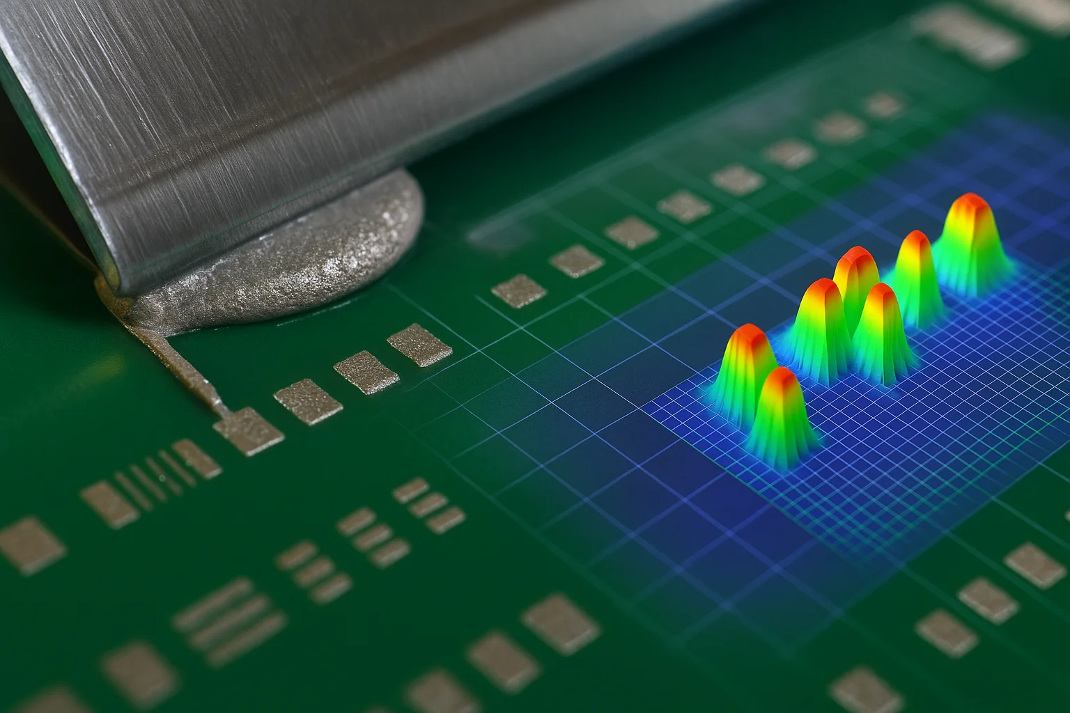
Step 2 – 3-D Solder Paste Inspection (SPI)
- Goal: Verify paste volume, area and height before any components are wasted.
- Metrics: < 5 % volume variation pad-to-pad; Cpk ≥ 1.33 on height.
- Action loop: SPI data feeds back to the printer to auto-correct stencil alignment or squeegee pressure, turning the print stage into a closed-loop process.
Step 3 – Pick-and-Place: Component Mounting
- Goal: Place every SMD within ±30 µm at rates above 30 000 CPH per module.
- Feeder strategy: Group high-volume passives on turret heads; dedicate precision vision nozzles for µBGAs, 0201 caps and 0.4 mm-pitch QFNs.
- Design tip: Provide fiducials and local pad targets so vision systems can correct board stretch and skew in real time.
Step 4 – Reflow Soldering
- Goal: Create shiny, void-free solder joints without damaging components.
- Profile stages:
- Pre-heat (ramp 1–3 °C/s) to activate flux and reduce ΔT.
- Soak (150–180 °C) to equalize board mass.
- Reflow/Peak (235–245 °C for SAC305; <225 °C for low-temp) 30–60 s above liquidus.
- Cool (–3 °C/s max) to solidify grains.
- Monitoring: Dual thermocouples on the heaviest and lightest thermal masses validate that time-above-liquidus (TAL) stays within spec (40–90 s).
Step 5 – Automated Optical Inspection (AOI)
- Goal: Catch opens, bridges, polarity errors and lifted leads immediately after reflow.
- Resolution: down to 10 µm/pixel with angled-camera shadow elimination for 01005 parts.
- Programming tip: Start with CAD netlist import, then fine-tune threshold libraries using golden-board images to cut false calls < 200 PPM.
Step 6 – X-ray (AXI/µCT) for Hidden Joints
- When needed: BGAs, LGAs, QFNs, bottom-terminated packages and power modules.
- Inspection targets: void ratio < 25 % in thermal pads; consistent inter-ball stand-off; no head-in-pillow (HIP) or non-wet opens (NWO).
- Advanced KPI: Automated 3-D voxel analysis correlates void location with thermal cycling reliability data.
Step 7 – In-Circuit & Functional Test (ICT/FCT)
- ICT: Bed-of-nails probes check shorts/opens, component values and microcontroller programming in < 1 s/board.
- FCT: Powers the board to exercise real-world I/O, often via boundary-scan (JTAG) or custom fixtures.
- DFT rules: Add test pads on every net ≥0.9 mm diameter with ≥1.3 mm pitch; keep copper free of soldermask for pogo-pin contact.
Step 8 – Final Processes: Cleaning, Conformal Coating & Packaging
- Cleaning (if required) to remove flux residues—aqueous, semi-aqueous or vapor phase, validated to IPC-TM-650 ionic contamination ≤1.56 µg NaCl eq/cm².
- Conformal Coating/Potting for high-reliability or harsh-environment boards (IPC-CC-830).
- Laser Mark & Serialization for traceability—link each assembly to lot/date and X-ray/AOI data.
- Packaging: ESD-safe trays, tape-and-reel or vacuum barrier bags; include humidity indicator cards for moisture-sensitive devices.
Process Control Takeaways
- Closed-Loop Data: SPI → Printer and AOI/AXI → Pick-and-Place offsets reduce drift and improve Cpk across shifts.
- Profile Verification: Record every reflow run; build a statistical library to catch heater drift early.
- Yield Math: Y = (1 – DPMO/1 000 000)ⁿ where n = components per board. Even a 99.9 % placement accuracy yields just 74% for a 250-component board—hence the need for rigorous inspection gates.
By internalizing this eight-step workflow—from first stencil stroke to final vacuum seal—you'll design boards that glide through production, minimize rework and reach mass-market scale on schedule and under budget.
Design for SMT ― DFM, DFT & Package Sizing Guidelines
Efficient surface-mount PCB assembly begins long before the first board hits the line; it starts in your CAD tool. By baking manufacturability and testability into the layout, you cut re-spins, improve yield, and shorten time-to-market.
1. Design for Manufacturability (DFM) ‐ Land-Pattern & Layout Rules
| Item | Best-Practice Guideline | Why It Matters |
|---|---|---|
| Land-pattern library | Base footprints on the latest IPC-7351 family (e.g., IPC-7351C “Density Level B” for general-purpose boards). Override pads only for special reflow profiles. | Ensures paste-to-pad area ratio stays within 0.66-0.75, preventing tombstoning or mid-chip solder beading. |
| Copper-to-solder-mask clearance | ≥ 75 µm for <0.5 mm-pitch QFNs/BGAs; ≥ 100 µm for standard passives. | Prevents mask slivers that trap flux and lift during reflow. |
| Via-in-pad | Plug & plate micro-vias (≤ 0.3 mm) on BGA pads; keep-out unfilled vias within 0.5 mm of any pad. | Unfilled vias wick solder, starving the joint. Filled + capped vias keep solder volume consistent. |
| Component keep-out & fiducials | 3 mm around global fiducials; 1 mm for local (BGA corner) fiducials. | Gives pick-and-place cameras clear contrast for ±25 µm placement repeatability. |
| Panelization | Add 3-edge tooling rails (≥ 5 mm) plus break-away mouse-bites every 75 mm. Locate v-grooves ≥ 1 mm from copper. | Stabilizes thin boards during conveyor transport and automated depaneling. |
Pro-tip: Keep identical orientation for polarized parts (tantalum caps, LEDs) in the same XY row; this reduces feeder changes and pairs with AOI polarity libraries.
2. Stencil & Paste Optimisation
Stencil Thickness
- 0.10–0.12 mm for 0.5 mm-pitch BGAs/QFNs and 0201 passives.
- Step-up windows (0.15 mm) under large power inductors to deliver extra paste volume.
Aperture Modifications
- "Home-plate" or "inverted-home-plate" cuts paste volume ~15 % at QFP lead tips, eliminating heel bridging.
- "Window-pane" walls on big pads (>3 × 3 mm thermal pads) equalise outgassing, minimising voiding under power MOSFETs.
Paste Selection
- SAC305 (Sn96.5/Ag3/Cu0.5) remains the mainstream alloy; switch to low-temp Bi-Sn57 for flexible-polyimide or heat-sensitive LEDs.
- Choose Type 5 (15–25 µm) powder for 0.4 mm-pitch; Type 6 (5–15 µm) for 0.3 mm-pitch µBGAs.
3. Design for Test (DFT)
| Technique | Layout Recommendation | Benefit |
|---|---|---|
| Bed-of-nails ICT | Ø 0.9 mm, pitch ≥ 1.3 mm test pads on every net; place pads on 50 mil grid for fixture spring probes. | Finds shorts/opens, resistor/cap values, MCU program, in <1 s. |
| Boundary-scan (JTAG) | Buffer the chain with 0 Ω links so unused boards can depopulate tap-controllers; route Test Reset & Test Clock clear of high-speed nets. | Flash-programming & structural test without extra pads. |
| Edge-connector test | Add 3-5 mm "dwell" zone beyond edge fingers; gold-plate for low contact resistance. | Allows functional test fixtures without pogo pins. |
| DFT for AOI | Keep polarity marks visible from top camera: chamfered pad on tantalum caps, dot silk on IC Pin 1; avoid placing tall electrolytics adjacent to 0201 passives. | Slashes false calls; boosts AOI first-pass yield > 95 %. |
Rule-of-thumb: Every 1 mm² you devote to test pads during layout saves 10 minutes of troubleshooting during production debug.
4. Package Size & Pitch Selection
| Package | Typical Pitch / Body | Recommended Pad Length (mm) | Stencil Aperture (%) | Notes |
|---|---|---|---|---|
| 0603 (1608 metric) | – | 0.90 | 100 % | "Entry level" SMT—hand-rework friendly. |
| 0402 (1005) | – | 0.65 | 100 % | Common on IoT & wearables. |
| 0201 (0603) | – | 0.40 | 90 % | Requires Type 5 paste; cleanroom SMT line strongly advised. |
| 01005 (0402) | – | 0.25 | 85 % | Reflow ΔT < 3 °C across board; AOI pixel ≤ 7 µm. |
| µBGA 0.5 mm | 0.5 mm | 0.30 | 90 % | Dog-bone fan-out with micro-vias in pad. |
| µBGA 0.3 mm | 0.3 mm | 0.18 | 80 % | Mandatory laser-drilled capped micro-vias; Type 6 paste. |
When to stop shrinking: below 01005 and 0.3 mm pitch, yield loss accelerates unless you upgrade to nitrogen reflow, under-stencil cleaning every 3 prints and SPI pixel ≤ 10 µm.

Quality & Inspection — Building Zero-Defect SMT Assemblies
Consistent SMT assembly quality is achieved by layering inspection gates, statistical process control and rigorous reliability testing.
The framework below shows how world-class factories drive ≤ 25 DPMO and > 99.8% first-pass yield while keeping costs in check.
1. The "Inspection Pyramid"
▲  Level 5  Environmental & Reliability  (sample)
│  Level 4  Functional / System Test     (100% or sample)
│  Level 3  In-Circuit Test (ICT)        (100%)
│  Level 2  X-ray (AXI / µCT)            (selective)
│  Level 1  AOI + SPI                    (100% inline)
└────────── Prevention (DFM / DFT / SPC)
- Inline gates (Levels 1–2) catch > 80 % of defects before costly rework.
- Electrical gates (Level 3) validate circuit integrity.
- End-use gates (Levels 4–5) prove long-term reliability.
2. Inline Optical & Paste Inspection
| Gate | KPI Goal | Typical Equipment Specs | Design / Process Tips |
|---|---|---|---|
| SPI (Solder Paste Inspection) | Volume Cpk ≥ 1.33 ; Height ±15 % | 3-D moiré, 10 µm Z-resolution | Keep aperture area ratio 0.66–0.75; wipe stencil every 5 prints. |
| AOI (Automated Optical) | False-call < 200 PPM ; Escape < 20 PPM | 15 MP cameras; 10 µm/pixel; 8-direction lighting | Place polarity marks top-side; avoid tall cans beside 0201 parts. |
3. X-ray Inspection (AXI / µCT)
- When: BGAs, LGAs, bottom-terminated QFNs and power modules.
- Metrics:
- Void ratio < 25 % (thermal pad); < 10 % (RF ground);
- Head-in-Pillow (HIP) incidence < 500 PPB.
- 2025 trend: AI-driven voxel analysis flags sub-surface micro-cracks invisible to 2-D projections, cutting analysis time 40 %.
4. In-Circuit & Functional Test
| Test | Coverage | Key Layout Rules | Benefit |
|---|---|---|---|
| ICT | Shorts, opens, R/C/L, flash programming | Ø0.9 mm pads on 1.27 mm grid; isolate high-voltage nets (>50 V) | < 1 s/board; 98 % structural fault detection |
| Boundary-Scan / JTAG | Digital nets, BGA balls inaccessible to ICT | Provide TRST, TCK, TDI, TDO, TMS with 0 Ω links | Removes 40+ ICT probes, lowering fixture cost |
| Functional / Burn-In | Full power-on, I/O loopback, load test | Edge connector dwell zone ≥ 3 mm; gold-flash | Finds interaction faults missed by ICT; proves firmware |
5. Environmental & Reliability Testing
| Stress Method | Typical Spec (Consumer / Automotive) | Common Failure Modes Detected |
|---|---|---|
| Thermal Cycling (−40 → 125 °C, 1000 cycles) | ΔR/R < 5 % ; no solder fatigue | Pad-lift, barrel cracking, brittle joints |
| Power Cycling | 10 k on/off, 4 A load | MOSFET void-induced hot-spots |
| HAST / Damp-Heat (85 °C/85 % RH, 96 h) | No corrosion; ICT pass | Flux residue ionics, mask delamination |
| Random Vibration (10–2 k Hz, 8 Grms) | No cracked MLCCs, connector drop-outs | Solder fillet resonance, potting voids |
Adopt JEDEC JESD22 or IPC-9701 profiles appropriate to product class (consumer, industrial, medical, automotive).
6. Defect-Cause-Countermeasure Matrix
| Defect | Typical Cause | Detection Gate | Immediate Fix | Preventive Action |
|---|---|---|---|---|
| Tombstoning 0402 | Uneven paste volume; thermal imbalance | AOI | Rework hot-air | Reduce pad length 10 %; balance copper pour |
| Shorts under µBGA | Excess paste; stencil mis-alignment | AXI | Hot-bar reball | Step-down stencil; tighten SPI Cpk |
| Head-in-Pillow | Poor wetting; warpage mismatch | AXI | Hot-air reflow | Increase TAL 10 s; switch to low-void paste |
| Opens after thermal shock | Via-in-pad wicking | ICT / Thermal cycle | Micro-solder patch | Plug & cap micro-vias; add anchor dog-bone |
7. Metrics & Continuous Improvement
| Metric | World-Class Target | Calculation |
|---|---|---|
| DPMO (Defects Per Million Opportunities) | < 25 | (Defects × 1 000 000) ÷ (Units × Opportunities) |
| First-Pass Yield (FPY) | > 99.8 % | Good units ÷ Total units (no rework) |
| Cp / Cpk (Stencil, placement) | ≥ 1.33 | (USL – LSL) ÷ 6σ ; shifted for mean |
Run real-time SPC dashboards on SPI and AOI data; trigger Kaizen events when Cpk drifts below 1.25 or false-calls exceed 300 PPM.
8. Compliance & Certification Check-List
- IPC-A-610 H Class 2 or 3 acceptance criteria archived and signed.
- IPC-J-STD-001 process control logbooks stored ≥ 10 years.
- Quality-system certified to ISO 9001:2015; automotive lines to IATF 16949.
- Solder alloys traceable to RoHS/REACH lot numbers; MSDS on file.
Bottom Line
Implementing a layered SMT inspection strategy—from SPI to environmental stress—cuts cost of poor quality (COPQ) by up to 70% compared with a purely reactive approach.
In the following module we'll quantify cost drivers and real-world pricing models so you can link every extra inspection step to tangible savings on scrap, rework and warranty claims.
Cost Drivers & Quote Calculation Example
1. What Really Moves an SMT Assembly Quote?
| Cost Bucket | Typical Range* | Primary Levers |
|---|---|---|
| NRE / Setup (stencil, program, line change-over) | US $ 80 – 400 per run | # of unique jobs per day, stencil type, programming time |
| Bare-PCB Fabrication | US $ 0.05–0.25 / cm² (2-layer) → 2-3× for 6-layer | board size, layer count, HDI features, finish |
| Components (BOM) | 40 – 70 % of total cost | AVL pricing, alternates, supply constraints |
| Placement Cost (machine + labor) | US $ 0.02 – 0.10 per SMT “point”; US $ 0.08 – 0.15 per THT pin | part pitch, feeder changes, fine-pitch/BGA count |
| Special Processes | +10 – 30 % | BGA reball, under-fill, selective wave, conformal coat |
| Test & Inspection | US $ 0.50 – 5.00 per board | ICT fixture amortization, AXI scan depth, functional burn-in |
| Logistics & Overhead | 5 – 15 % | freight, customs, yield buffer |
*Asia-Pacific 2025 averages; Western Europe/US typically 1.3 – 1.6 × higher.
2. A Universal SMT Cost Formula
Total Cost = (PCB Cost + BOM Cost)
          + (Setup / Qty)
          + (Σ SMT Points × Point Rate)
          + (Σ THT Pins × Pin Rate)
          + Test & Misc
This "stack" format is the same model many online calculators apply, simply hiding the arithmetic behind sliders.
3. Two Quote Scenarios
| Parameter | Prototype Build | Mid-Volume |
|---|---|---|
| Quantity | 10 boards | 1 000 boards |
| Layers / Size | 4-layer, 80 cm² | 4-layer, 80 cm² |
| Components / board | 100 SMT, 5 THT | 100 SMT, 5 THT |
| PCB Fabrication | US $ 50 ea | US $ 6 ea |
| BOM Parts | US $ 12 ea | US $ 10 ea |
| Setup (stencil, program) | US $ 120 (one-time) | US $ 120 (amortized) |
| Placement Rate | US $ 0.12 / SMT point | US $ 0.03 / SMT point |
| Test & Pack | US $ 4 ea | US $ 1.5 ea |
Cost per board
Prototype: PCB 50 + BOM 12 + Setup (120 / 10 = 12) + Placement (100 × 0.12 = 12) + Test 4 = US $ 90
Mid-Volume: PCB 6 + BOM 10 + Setup (0.12) + Placement (100 × 0.03 = 3) + Test 1.5 = US $ 20.62
Bittele's 2024 public example—US $ 6.40 per board for 1 000 units with 125 placements—falls in the same ballpark when BOM is low-cost.
Takeaway: Setup and placement rates dominate at low volumes; by 1 000 + pcs, BOM becomes the #1 driver of SMT assembly cost.
4. Five Fast Ways to Slash Your Quote
- Panelize for Efficiency – keep panel utilisation > 80 %; fewer starts means lower setup amortisation.
- Consolidate the BOM – authorised alternates cut part price variance by 10–15 %.
- Minimise Special Steps – avoid via-in-pad unless density demands it; each custom process adds ~10 % overhead.
- Aim for Volume Breakpoints – unit price often drops ~20 % at 250, 500 and 1 000 pcs thanks to machine utilisation.
- Use an Online Cost Calculator Early – enter size, layers and component count to test “what-ifs” before locking the schematic.
Frequently Asked Questions (FAQ)
What is the difference between SMT and THT assembly?
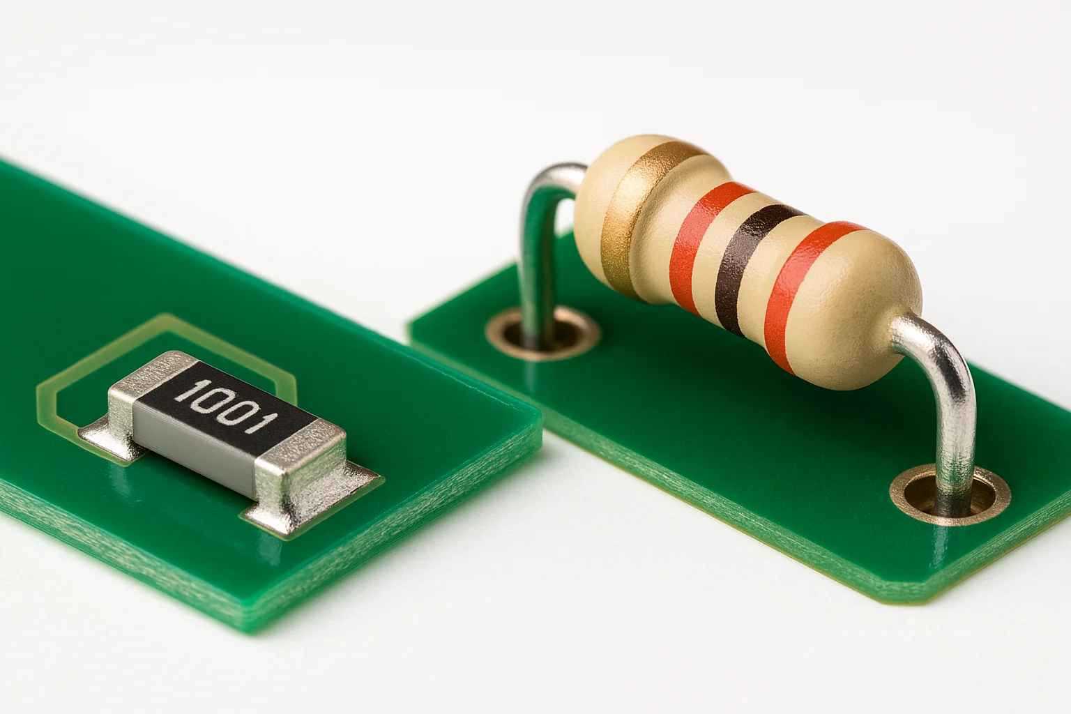
Surface-mount technology (SMT) places components directly onto copper pads and is fully automated, whereas through-hole technology (THT) inserts leads through drilled holes and is often wave-soldered or hand-soldered. SMT enables higher component density, smaller boards and faster production; THT offers stronger mechanical anchoring for bulky or high-stress parts.
How small can the components be in modern SMT assembly?
State-of-the-art lines routinely place 01005 passives (0.4 × 0.2 mm) and 0.3 mm-pitch micro-BGAs with placement accuracy better than ±30 µm when Type-6 solder paste and 10 µm-pixel SPI/AOI are in place.
What files are needed for an accurate SMT assembly quote?
Provide the full Gerber/ODB++ or IPC-2581 package, an XY Centroid/Pick-and-Place file, the BOM with approved alternates, assembly drawings (PDF) and any test requirements (ICT, FCT). Including expected order quantity and target schedule speeds up cost modelling.
What is the typical lead time for SMT PCB assembly?
Prototype runs (≤ 20 boards) can ship in 3–5 working days with pre-stocked parts. Standard production batches (100 – 5 000 pcs) take 10–15 working days, subject to component availability and stencil fabrication.
Is there a minimum order quantity (MOQ)?
Most EMS providers accept as low as 1–10 pieces for prototypes but apply higher setup fees. Cost per board drops sharply at common breakpoints—100, 250 and 1 000 units—when machine utilisation improves.
How can I reduce SMT assembly cost?
Panelise boards for > 80 % utilisation, consolidate the BOM around stocked alternates, avoid special processes like via-in-pad unless essential, and lock purchase orders at volume tiers to secure component price breaks.
Which inspection methods ensure quality?
A layered approach—SPI → AOI → (optional) AXI → ICT/Functional test—catches > 99 % of defects before shipment and supports DPMO targets below 25.
Does SMT assembly comply with RoHS/REACH?
Reputable suppliers trace solder alloy lots and component certifications to guarantee RoHS 3 and REACH compliance. Always request certificates of conformity with each shipment.
Conclusion & Next Steps
By now you have a 360-degree view of SMT PCB assembly—from the fundamentals and process flow to cost modelling, supplier vetting and the road ahead with 01005 and AI-powered inspection. Whether you're shrinking the next wearable, ruggedising an industrial controller or racing a startup prototype to investors, leveraging the design-for-manufacture tactics in this guide will:
- Cut board area by up to 30% through tighter package selection and balanced copper layouts.
- Raise first-pass yield above 99.8% thanks to closed-loop SPI ⇒ AOI ⇒ ICT inspection gates.
- Slash cost per unit 2–5× as volumes climb past the key 250- and 1000-piece breakpoints.