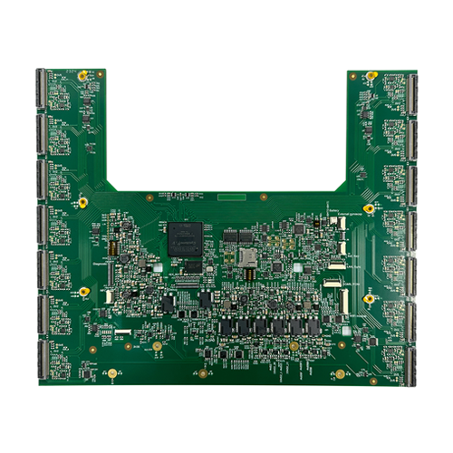
Rigid-Flex PCB

18-Layer Rigid-Flex PCB for Aerospace


Layers 18L(4R+10F+4R)
Thicknes 2.1±0.02mm
Size 287.88*421.05mm
Min. Buried Via/PAD

Min. Distance from Via to Line

0.4mm/1.0mm

0.3mm

Hole Wall Copper Thickness

Surface Treatment

30um

ENIG

ARLON PI Material Special Control during Lamination

Applications

Impedance Control

Mother Board of Aerial Tanker Control System

This 18-layer Rigid-Flex PCB (4R + 10F + 4R) is engineered for mission-critical aerospace applications, specifically used in the motherboard of an aerial tanker control system. With a precise total thickness of 2.1±0.02mm and dimensions of 287.88mm x 421.05mm, it combines structural rigidity with the routing flexibility needed in compact, high-density designs.

The board features fine buried via and pad tolerances (0.4mm/1.0mm), controlled impedance of 50±10%, and high-reliability ENIG surface treatment. Special process controls are applied during lamination to manage ARLON polyimide materials, ensuring thermal stability and long-term reliability under extreme operating conditions.

Specifications:

  • Type: Rigid-Flex PCB

  • Layers: 18 (4R + 10F + 4R)

  • Thickness: 2.1±0.02mm

  • Size: 287.88mm x 421.05mm

  • Min. Buried Via / PAD: 0.4mm / 1.0mm

  • Min. Distance from Via to Trace: 0.3mm

  • Hole Wall Copper: 30μm

  • Impedance: 50±10%

  • Surface Finish: ENIG

  • Material: ARLON Polyimide with Controlled Lamination Process

  • Application: Aerospace – Aerial Tanker Control System Motherboard

To ensure the highest performance and manufacturability of this complex Rigid-Flex PCB, the following requirements must be considered during the design and production phase:

  • Layer Stack-up Clarity: Provide a detailed stack-up file indicating rigid and flex zones with impedance layer mapping.

  • Material Call-Out: Specify high-temp ARLON PI material explicitly in the BOM and design notes.

  • Flex Routing: Avoid sharp corners and allow for sufficient bend radius, especially in flex-to-install zones.

  • Via Management: Blind/buried via structures must meet IPC-6013 Class 3A standards for aerospace.

  • Thermal Stress Simulation: For aerospace use, consider FEA validation or thermal cycle simulation data in design validation.

  • Documentation: IPC-2223-compliant drawings and clear lamination stage instructions are required.

Q1: Why is ARLON PI material used in this Rigid-Flex PCB?
A1: ARLON polyimide materials provide excellent thermal resistance, dimensional stability, and electrical performance — making them ideal for aerospace environments where temperature cycling and reliability are critical.

Q2: What challenges does the 18-layer Rigid-Flex structure pose?
A2: Complex lamination cycles, precision alignment between rigid and flexible zones, and managing warpage are key challenges. Our manufacturing process includes special lamination controls to ensure structural integrity and performance.

Q3: Can impedance values be customized?
A3: Yes, we support custom impedance tuning. Please specify your target impedance and reference layer configuration during the design phase.

Q4: How do you ensure via reliability in aerospace environments?
A4: We follow Class 3A standards with high copper plating thickness (≥30μm) and use strict via-hole integrity testing including thermal shock and cross-section analysis.

Q5: What is the typical lead time for such a complex PCB?
A5: Lead times vary based on design complexity and validation needs. For this 18-layer Rigid-Flex board, the typical production cycle is 20–25 working days, subject to DFM review.

Sharing is caring

Get in touch

Leave us a message

Please enable JavaScript in your browser to complete this form.