

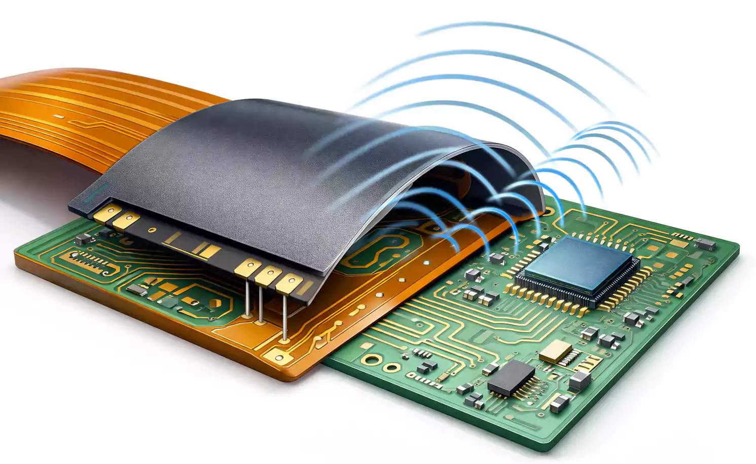

Flexible printed circuits are used in products that need to bend, fold, or fit into tight spaces. You will find them in medical devices, cameras, wearables, automotive electronics, and many other compact products.
But the copper traces on a flex PCB cannot stay exposed. They need protection. That protection must also stay flexible, or the circuit may crack or fail during use.
That is where coverlay comes in.
Quick Answer: What Is Flex PCB Coverlay?
Flex PCB coverlay is a flexible protective layer laminated over the outer copper traces of a flexible circuit. It is usually made from polyimide film and adhesive.
Its main job is to:
- Protect the copper traces
- provide electrical insulation
- improve durability during bending
- shield the circuit from moisture, dust, and handling damage
You can think of coverlay as the flex PCB version of solder mask, but it is designed for circuits that must bend and move.
What Is Flex PCB Coverlay?
Coverlay is a flexible insulating layer used to cover the exposed outer copper circuits of a flex PCB.
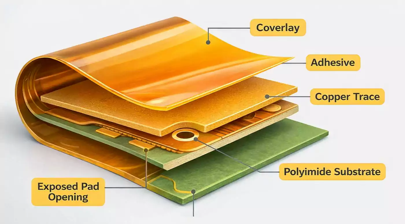
It is typically made of two layers:
- a polyimide film
- an adhesive layer
The polyimide film provides flexibility, heat resistance, and mechanical strength. The adhesive bonds the film to the circuit surface and seals the copper underneath.
In some manufacturing documents, coverlay may also be called cover film or covercoat film.
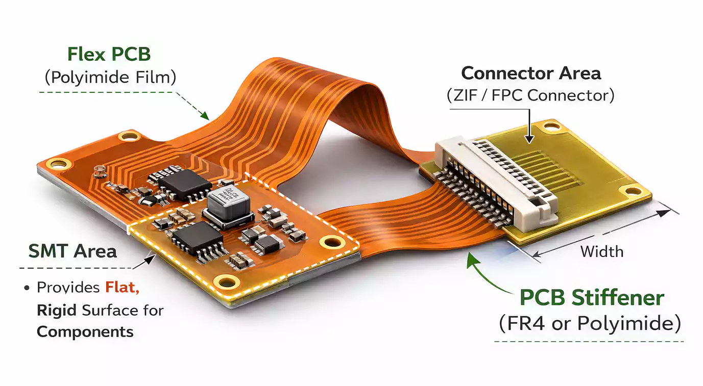
In a typical flex PCB structure, the copper traces sit on a flexible base material, often polyimide. The coverlay is then laminated on top, with openings only where pads, connectors, or soldering areas need to stay exposed.
This is why coverlay is not the same as standard solder mask on a rigid PCB. It is not just a thin liquid coating. It is a separate flexible film bonded onto the circuit.
Why Is Coverlay Used in Flex PCBs?
Coverlay does much more than simply cover the circuit. It plays an important role in both performance and reliability.
1. Protects the copper traces.
Flex PCB copper circuits are thin and easy to damage during handling, assembly, or repeated movement.
Coverlay helps protect them from:
- scratches
- abrasion
- impact
- contamination
This is especially important in products where the flex circuit moves during use or fits into a cramped mechanical space.
2. Provides electrical insulation.
The outer copper on a flex PCB must be insulated from the environment and from nearby conductive parts.
Coverlay helps prevent short circuits and keeps the circuit electrically stable.
3. Supports bending reliability.
A flex PCB must remain flexible after the protective layer is applied.
Coverlay is designed to bend with the circuit. This makes it much more suitable than brittle coatings in applications that require repeated flexing.
4. Improves environmental resistance.
Coverlay also helps protect the circuit against:
- dust
- moisture
- chemicals
- general environmental exposure
That makes it valuable in industrial, automotive, and medical applications where long-term reliability matters.
5. Protects during soldering and assembly.
Only certain areas of the circuit should remain exposed for soldering or connection.
Coverlay helps define those exposed areas while keeping the rest of the copper protected.
What Is Flex PCB Coverlay Made Of?
Most standard flex PCB coverlay uses polyimide film with adhesive.
This is the most common structure because it offers a strong balance of flexibility, protection, and manufacturability.
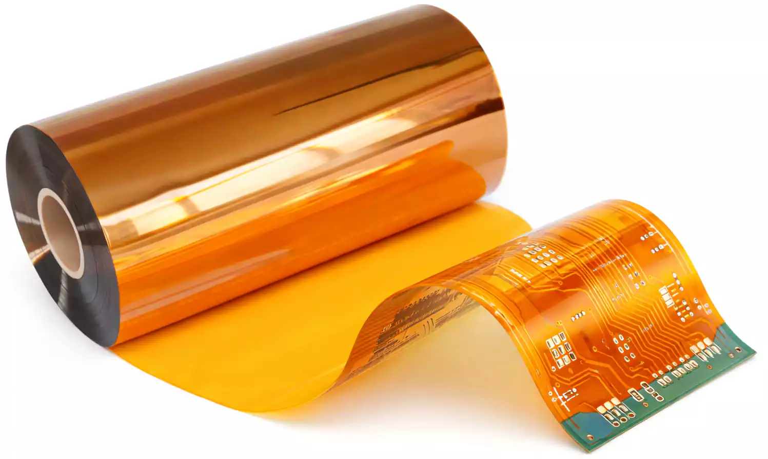
1. Polyimide film
Polyimide is widely used because it offers:
- excellent flexibility
- strong heat resistance
- good mechanical strength
- stable dielectric performance
- reliable performance in harsh environments
It is also commonly used in flex PCB base materials, making it well-suited as an outer protective layer.
2. Adhesive layer
The adhesive bonds the polyimide film to the copper circuit.
It must be thick enough to flow over the copper features during lamination and fully seal them. At the same time, it must stay controlled enough to avoid poor registration or unwanted squeeze-out.
That is why adhesive thickness is an important part of coverlay selection.
How Is Coverlay Applied?
In manufacturing, coverlay is usually prepared with openings for pads, connectors, and component areas.
Those openings may be created by:
- routing
- drilling
- punching
- laser cutting
After that, the coverlay is aligned to the circuit pattern and laminated under heat and pressure.
During lamination, the adhesive bonds the coverlay to the flex circuit surface and seals the copper traces underneath.
The result is a protected and insulated flexible circuit, with only the required contact areas left open.
How to Choose the Right Coverlay Thickness
Coverlay thickness affects flexibility, protection, manufacturability, and long-term reliability.
A common standard choice is:
1 mil polyimide film + 1 mil adhesive
This 1:1 combination is widely used because it gives a good balance between protection and flexibility.
Still, the right thickness depends on the design.
1. Minimum bend radius
If the circuit must bend tightly, a thinner coverlay is usually better.
A thinner structure reduces stiffness and allows the flex area to move more easily.
This is especially important for dynamic bending applications.
2. Finished copper thickness
Thicker copper needs enough adhesive to fully encapsulate the copper profile.
A useful rule of thumb is:
For each 1 oz of finished copper, use about 1 mil of adhesive as a starting point.
This helps ensure the copper is properly covered and sealed.
3. Electrical insulation requirements
In some applications, coverlay also contributes to dielectric strength.
If the design involves higher voltages or stricter insulation requirements, thickness may require additional consideration.
4. Mechanical durability
Some circuits require additional protection against stress, mechanical wear, or surface contact.
In those cases, a thicker coverlay may improve durability, even if it slightly reduces flexibility.
5. Cost
Thicker or more specialized coverlay constructions can increase material and process costs.
The best approach is not to choose the thickest option by default, but to match the coverlay to the real design need.
Flex PCB Coverlay vs. Solder Mask
This is one of the most common questions in flex PCB design.
Both coverlay and solder mask protect outer copper circuits, but they are not the same material, and they are not used in the same way.
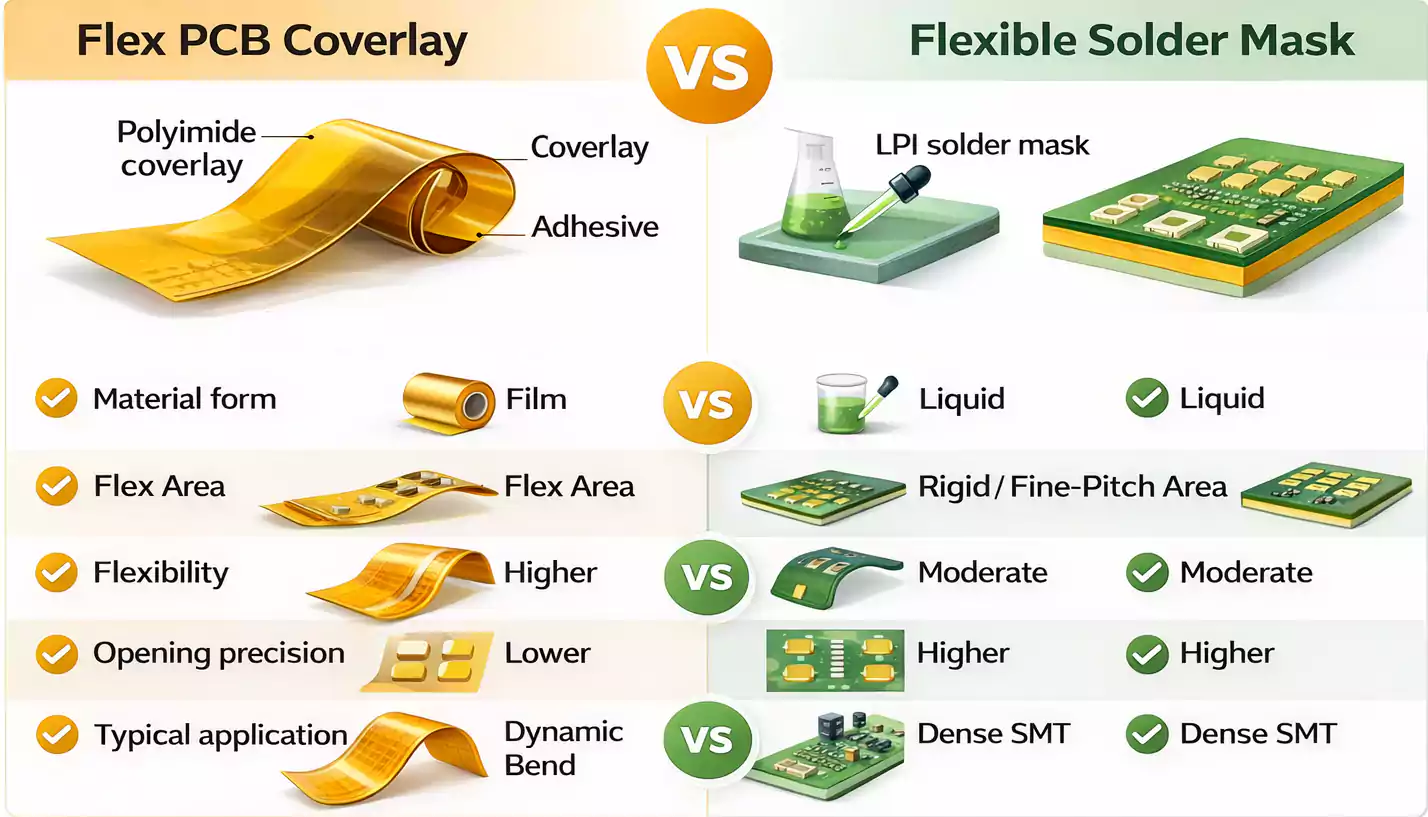
1. Material type
Coverlay is a film-based material made from polyimide and adhesive.
Solder mask is usually a liquid photoimageable coating or similar liquid-applied resist.
That basic difference affects how each one performs.
2. Flexibility
Coverlay is built for flexible circuits.
It bends with the board and is generally better for long-term flexing and repeated movement.
A flexible solder mask can work in some flex designs, but it usually does not match the coverlay in dynamic bending durability.
3. Opening precision
Solder mask is patterned by imaging, so it can usually support finer features and smaller openings.
Coverlay uses pre-cut openings, so its opening size and registration limits are generally larger.
That makes coverlay less suitable for very fine-pitch component areas.
4. Dam and clearance
Coverlay usually needs larger dams and larger clearances than solder mask.
This matters in high-density layouts where pads are close together.
5. Typical applications
In many designs:
- Coverlay is preferred in the flex areas
- Solder mask is more common in rigid areas
- In rigid-flex PCBs, both may be used on different parts of the same board
Design Tips for Flex PCB Coverlay
Choosing the material is only part of the job. Good design practice is just as important.
1. Match adhesive thickness to copper thickness.
If the adhesive is too thin, it may not fully cover the copper profile.
That can lead to poor sealing, weaker insulation, or reliability issues.
2. Size openings carefully
Pad openings and connector openings should be large enough for assembly, but not so large that they reduce protection or weaken the surrounding area.
3. Allow for registration tolerance.
Because coverlay is mechanically aligned during lamination, it usually needs more design tolerance than photoimageable solder mask.
Adequate clearance helps prevent defects caused by small alignment shifts.
4. Avoid stress points in active bend areas.
If the flex section bends often, avoid placing seams, transitions, or unnecessary structural changes in the most active bend region.
A smoother bend area usually improves fatigue life.
5. Treat rigid-flex by region.
In a rigid-flex PCB, the rigid and flex sections do not always need the same outer protection method.
Coverlay may be ideal in the flex zone, while solder mask may be better in the rigid zone.
Advantages of Coverlay
Coverlay remains the standard choice in many flex PCB applications for good reasons.
Its main advantages include:
- strong flexibility
- good copper protection
- reliable electrical insulation
- better performance in bending applications
- good heat and environmental resistance
- long-term durability in moving circuits
Limitations of Coverlay
Coverlay is not perfect for every situation.
Its main limitations include:
- larger openings than the solder mask
- less suitable for ultra-fine-pitch components
- more design and alignment constraints
- Higher manufacturing complexity in some cases
- potentially higher cost than liquid-applied solder mask
These limitations do not make coverlay a poor choice. They simply mean it must be used where its strengths matter most.
FAQ
What is the difference between solder mask and flex coverlay?
Solder mask is usually a liquid-applied protective coating. Flex coverlay is a laminated polyimide film with adhesive. Coverlay is generally better for flexible, bending areas, while solder mask is better for fine-feature imaging and rigid sections.
How thick should the flex PCB coverlay be?
A common standard is 1 mil polyimide film plus 1 mil adhesive, but the ideal thickness depends on copper thickness, bend radius, insulation needs, and mechanical protection requirements.
Is coverlay better for dynamic bending?
Yes. In most cases, coverlay is the better choice for repeated bending because it is designed to move with the flex circuit and provide stronger protection over time.
Can coverlay be used in rigid-flex PCBs?
Yes. Coverlay is often used in the flex portions of a rigid-flex PCB, while solder mask may be used in the rigid portions. Many rigid-flex designs use both.
Conclusion
Flex PCB coverlay is one of the most important materials in flexible circuit design.
It protects the copper, provides insulation, improves durability, and helps the circuit survive bending and real-world use. In most standard flex applications, it is the preferred outer protective layer because it is built for movement in a way that ordinary solder mask is not.
The right choice depends on the design. Copper thickness, bend requirements, pad spacing, and assembly density all matter. If the circuit must bend often, coverlay is usually the safer choice. If the design requires very fine openings, solder mask may be better in selected areas.
At FastTurnPCB, we understand that flex and rigid-flex designs require the right balance of reliability, manufacturability, and cost. Choosing the right coverlay is a key part of that balance.
