Relays are among the most important building blocks in modern electronics.
From cars and HVAC systems to industrial automation and PCB design, these electromechanical devices quietly use a small control signal to switch a much larger electrical load.
This guide covers what a relay is, how it works, wiring and testing, and the features of SPDT, DPDT, solid-state, and reed relays.
What Is a Relay and Why Do We Use It?
A relay is an electrically operated switch. It allows one circuit to control another, providing electrical isolation between the control and load sides.
In other words, you can use a 5 V or 12 V logic signal to control a 120 V or 240 V load—without the two circuits ever touching directly.
Unlike a manual switch that you flip by hand, a relay uses an electromagnet or semiconductor element to move its contacts automatically. That makes it perfect for remote control, automation, protection, and sequencing.
Typical applications include:
- Automotive systems (fuel pump, headlights, horn)
- Industrial control panels and motor starters
- HVAC compressors and thermostats
- Power distribution and protective relays
- Smart home and IoT switching modules
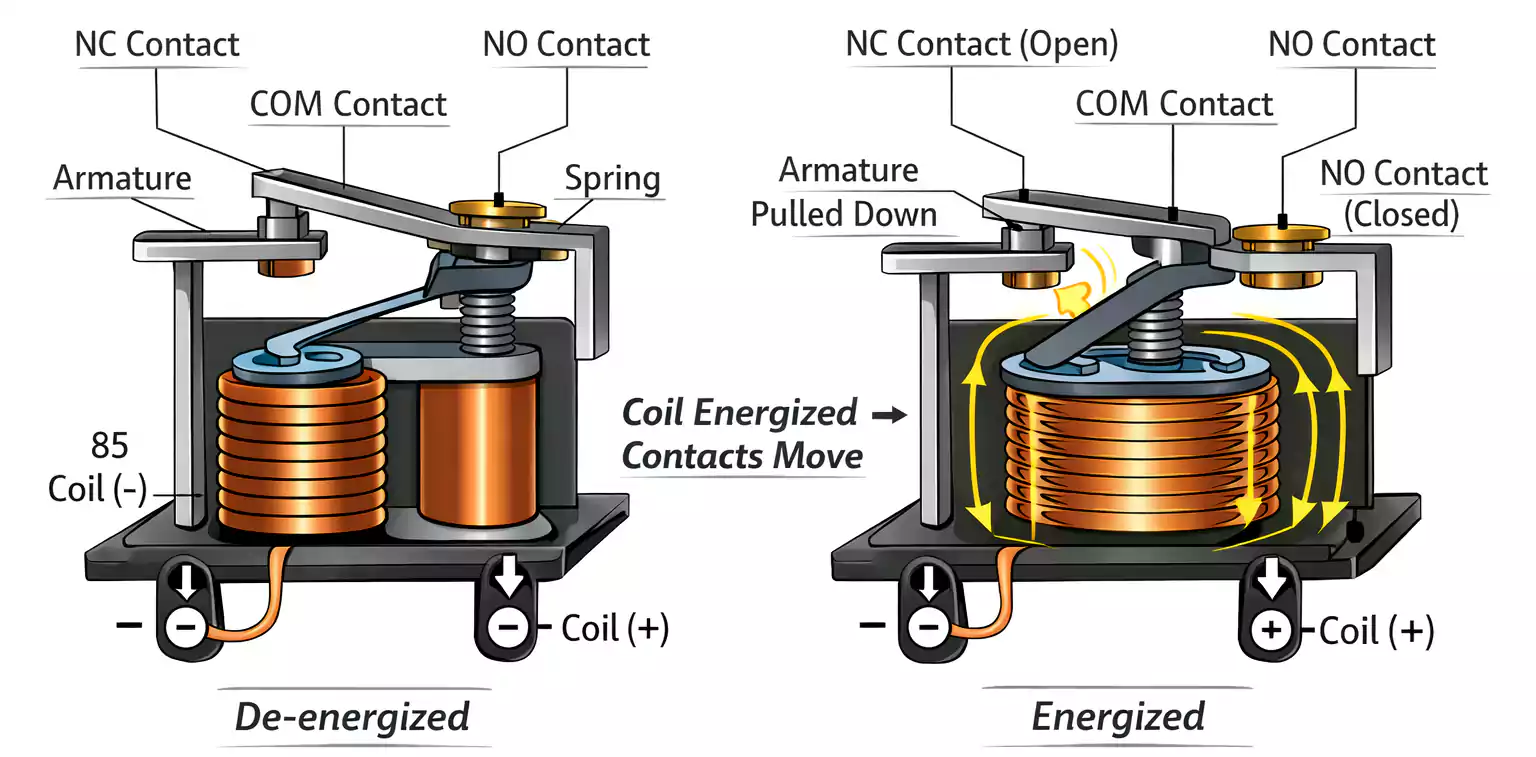
Inside a Relay: Coil, Armature, Spring, and Contacts
A mechanical relay—often called an electromagnetic relay (EMR)—has four key parts:
- Coil – a wire winding that becomes magnetic when current flows.
- Armature – a movable metal lever pulled by the magnetic field.
- Spring – returns the armature to its rest position when power is removed.
- Contacts – metal terminals that open or close the circuit.
When the coil is energized, it attracts the armature, changing the state of the contacts.
When power is removed, the spring pushes the armature back, returning the contacts to their default state.
Relays are defined by two common contact states:
- NO (Normally Open): Open when coil is off; closes when energized.
- NC (Normally Closed): Closed when coil is off; opens when energized.
This simple magnetic action makes relays reliable, galvanically isolated, and suitable for both AC and DC control.
Understanding Poles and Throws: SPST, SPDT, DPST, DPDT
Relays are categorized by how many circuits they control (poles) and how many output paths each circuit can take (throws).
| Type | Meaning | Description |
| SPST | Single-Pole, Single-Throw | One input, one output. Basic ON/OFF switch. |
| SPDT | Single-Pole, Double-Throw | One input switches between two outputs (NO/NC). |
| DPST | Double-Pole, Single-Throw | Two inputs switched simultaneously. |
| DPDT | Double-Pole, Double-Throw | Two SPDTs operating in sync—often used for polarity reversal. |
A DPDT (Double-Pole, Double-Throw) relay effectively contains two SPDT sections with linked armatures.
This is the go-to configuration for reversing the direction of a DC motor or toggling between two separate signal paths.
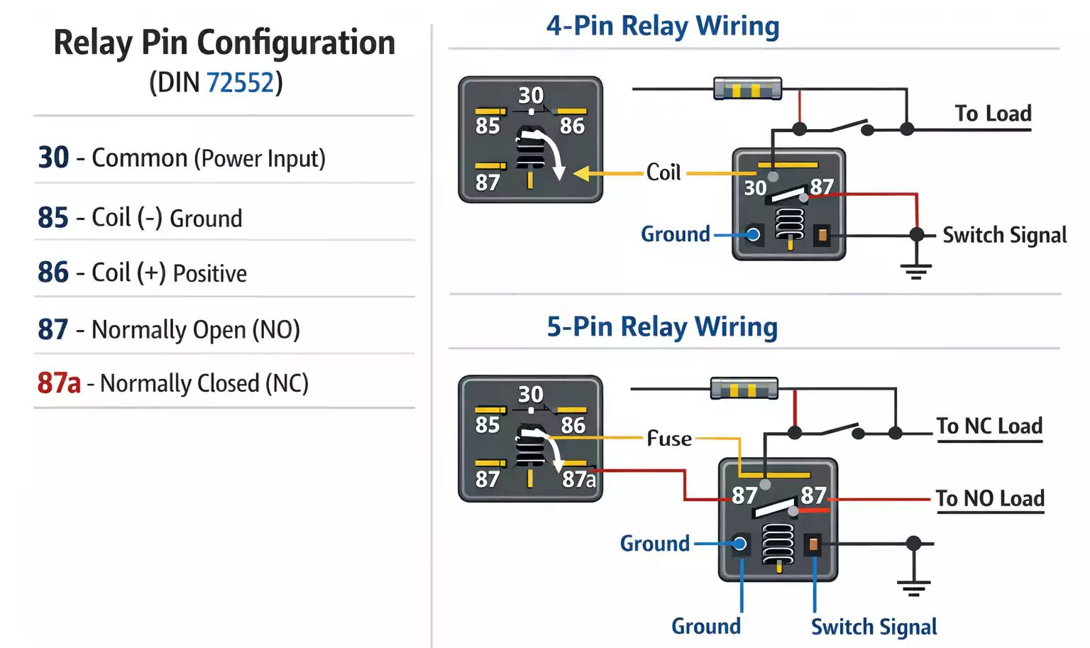
How to Wire a Relay (4-Pin and 5-Pin Types)
Relays are most commonly available in 4-pin or 5-pin automotive-style packages, standardized under DIN 72552.
Here’s what each terminal does:
| Terminal | Function |
| 30 | Common terminal (input from power or battery). |
| 87 | Normally Open contact (power out when energized). |
| 87a | Normally Closed contact (power out when NOT energized). Present only on 5-pin relays. |
| 85 | Coil terminal (ground side). |
| 86 | Coil terminal (positive side). |
4-Pin Relay (SPST or SPDT)
Terminals 30, 85, 86, 87.
When coil 85–86 is powered, 30 connects to 87, energizing the load.
5-Pin Relay (SPDT with Both NO and NC)
Adds 87a (NC).
When the relay is off, 30–87a are connected; when energized, 30–87 connects instead.
How to Test a Relay (3 Reliable Methods)
Testing ensures your relay is switching properly and that the coil and contacts are intact.
Here are three standard testing methods used by technicians and DIYers.
Method 1: Swap Test (Quick Check)
The fastest way: swap the suspect relay with an identical one from a working circuit.
If the problem moves, the relay is bad.
If not, the issue lies elsewhere (wiring, fuse, or control signal).
This works for automotive relays where multiple identical units are present.
Method 2: Multimeter Static Test (Coil and Contact Resistance)
- Check the coil:
- Set your multimeter to ohms.
- Measure across terminals 85 and 86.
- For a 12 V relay, you should typically see 50–120 Ω.
- Infinite Ω means an open coil; 0 Ω indicates a shorted coil.
- Check the contacts:
- With the relay unpowered, 30–87 should read open; 30–87a (if present) should read closed.
- Apply 12 V between 85 and 86 to energize the coil.
- Now 30–87 should close (0 Ω), and 30–87a should open.
Method 3: Dynamic Power Test (Listen and Measure)
Apply control voltage to the coil and listen for the click.
Simultaneously measure continuity across 30 and 87.
If you hear no click or the resistance doesn’t change, the relay may be jammed or internally burned.
Relay Testers: Faster, Safer, and Foolproof
A relay tester is a dedicated handheld tool that simplifies the tests described above.
It applies the proper voltage to the coil and automatically measures continuity between the contacts.
Most models can test 4-pin and 5-pin 12 V automotive relays, showing pass/fail indicators through LEDs.
They’re ideal for workshops handling multiple relays daily.
When choosing a tester, look for:
- Supported relay types (4/5 pins, 12 V DC)
- Built-in load simulation or LED indicators
- Clear pin labeling and polarity protection
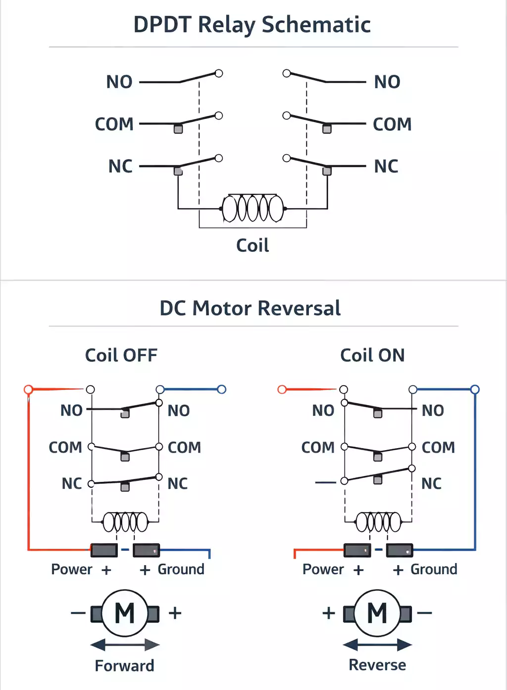
DPDT Relay Schematic Diagram and Wiring Examples
A DPDT (Double-Pole Double-Throw) relay can switch two independent circuits simultaneously.
Each side has a COM, NO, and NC contact.
1. DPDT Schematic Explained
     NO1   COM1   NC1
      |     |     |
      o-----/ ----o    (Pole 1)
      o-----/ ----o    (Pole 2)
      |     |     |
     NO2   COM2   NC2

When the coil is energized, both armatures move together—closing NO1/NO2 and opening NC1/NC2.
2. Common Wiring Applications
- DC Motor Reversal
- Signal or Power Source Switching
- Synchronized Dual Circuits
Always label each contact clearly on your schematic; mixing up COM and NO is a common beginner mistake.
Types of Relays: Mechanical, Solid-State, and Reed
Relays come in a wide variety, but three dominate most applications.
1. Electromechanical Relay (EMR)
- Classic coil-and-armature design.
- Handles high current (up to tens of amps).
- Provides galvanic isolation but produces audible clicks.
- Ideal for industrial control, HVAC, and automotive systems.
2. Solid-State Relay (SSR)
- Uses transistors, TRIACs, or optocouplers instead of contacts.
- No moving parts → silent, vibration-proof, and long life.
- Slight voltage drop and potential heat generation; requires heatsinking at high loads.
- Best for high-speed or high-cycle switching.
3. Reed Relay
- Tiny glass-sealed contacts operated by a small coil.
- Extremely fast and low current.
- Used in test instruments and RF switching.
When selecting a relay, match its coil voltage, contact rating, and switching speed to your application.
Common Relay Failures and Troubleshooting
Even good relays wear out over time.
Typical failure modes include:
- Pitted or welded contacts: from arcing or inrush current.
- Coil burnout: caused by overvoltage or continuous overheating.
- Mechanical jamming: debris or melted plastic blocking the armature.
- Socket corrosion or loose terminals: leading to intermittent operation.
If the relay passes testing but the circuit still fails, inspect:
- Socket connections for oxidation
- Fuse integrity
- Control voltage and ground continuity
Sometimes the relay is fine—the control circuit is the real culprit.
Frequently Asked Questions
What is a relay used for?
Relays are electrically controlled switches that allow low-voltage signals to safely and automatically control high-power devices.
How do I know if a relay is bad?
If your circuit doesn’t respond and you hear no click, test coil resistance and contact continuity.
Open coils, welded contacts, or no switching under power all indicate failure.
What do the numbers 30, 85, 86, 87, 87a mean?
They’re standardized DIN 72552 terminal numbers: 30 (power input), 87 (Normally Open output), 87a (Normally Closed output), 85 (coil −), 86 (coil +).
How do I test a 4-pin vs. a 5-pin relay?
The procedure is the same, but a 5-pin relay adds terminal 87a.
Check both 30–87 and 30–87a for correct switching behavior when energized.
Relay tester vs multimeter—what’s better?
A relay tester is faster for quick pass/fail checks, while a multimeter gives detailed readings of coil and contact resistance.
How do I wire a DPDT relay for motor reversal?
Cross the motor leads between the two poles so that each activation swaps polarity—always include a fuse and flyback diode for protection.
Final Thoughts
Relays may look simple, but mastering them bridges the gap between control logic and real-world power.
By understanding their structure, wiring, testing, and selection, you can design or troubleshoot circuits confidently—whether in an automotive harness, an industrial controller, or a custom PCB.
From “what is a relay” to “how to test and wire one safely,” this knowledge ensures reliable switching, longer component life, and fewer late-night debugging sessions.