


Introduction
Through-hole soldering is a key technique in electronics assembly, especially for DIY projects, prototyping, and components that need strong mechanical support. It involves inserting component leads into PCB holes and soldering them on the opposite side for a durable connection.
This tutorial provides a clear, step-by-step guide to through-hole soldering—including essential tools, soldering techniques, and tips to avoid common mistakes. Whether you're new to soldering or refining your skills, this guide will help you achieve clean, reliable solder joints
Fundamentals and Principles of Through-Hole Soldering
Through-hole soldering is the process of inserting component leads into drilled holes on a PCB and soldering them to pads on the opposite side. While surface-mount technology (SMT) dominates modern electronics, through-hole remains essential for prototyping, high-power components, and mechanical stability.
What Is Through-Hole Soldering?
In this method, component leads pass through plated-through holes (PTH) on the PCB. Solder is applied to bond the lead to the pad, creating both electrical connectivity and mechanical support.
There are two types of components:
- Axial-lead: Leads extend from both ends (e.g., resistors).
- Radial-lead: Both leads come from the same side (e.g., capacitors).
Why It Still Matters
Through-hole soldering is preferred for:
- Prototypes and testing
- Components under mechanical stress (e.g., connectors)
- DIY and educational projects
- Aerospace, automotive, and industrial applications
How It Works: Key Principles
- Heat Transfer: The soldering iron heats both the lead and pad.
- Wetting: Molten solder flows across surfaces to form a solid bond.
- Capillary Action: Solder fills the hole and wraps around the lead.
- Fillet Formation: A shiny, concave shape indicates a quality joint.
Through-Hole vs Surface Mount (Quick Comparison)
| Feature | Through-Hole | Surface-Mount |
|---|---|---|
| Component Size | Larger | Smaller |
| Assembly | Manual-friendly | Machine-based |
| Strength | Stronger joints | Less durable |
| Prototyping | Easier | Harder |
| Repairability | Easier | More difficult |
Essential Tools and Materials for Through-Hole Soldering
To achieve clean, reliable through-hole solder joints, having the right tools and materials is key. Here’s a quick overview of the essentials:
- Soldering Iron: Choose a temperature-controlled soldering iron with an appropriate tip size (chisel or conical works well for most through-hole jobs). A power rating of 30–60W is ideal for consistent heating.
- Solder Wire: Use 60/40 or lead-free solder with a diameter of 0.6–1.0mm. Rosin-core solder is recommended for electronics.
- Flux: Although many solder wires contain flux, using extra flux can improve wetting and reduce oxidation. Paste or pen-type flux is useful for precision.
- Desoldering Tools: A solder sucker or desoldering braid helps with corrections or component removal.
- Tweezers and Cutters: Anti-static tweezers help with positioning, and flush cutters are used to trim excess leads after soldering.
- PCB Holder or Third Hand Tool: Stabilizes the board during soldering, keeping your hands free.
- Magnifying Glass or Head Loupe: Helps inspect solder joints for proper wetting and shape.
- Safety Gear: Use fume extraction, eye protection, and work in a well-ventilated space to avoid inhaling fumes.
Step-by-Step Through-Hole Soldering Process
Mastering through-hole soldering requires more than just melting solder onto a joint. Each stage of the process plays a vital role in ensuring strong electrical connectivity and mechanical durability. Below is a detailed walkthrough of the complete through-hole soldering process, ideal for beginners and intermediate users.
1. Prepare Your PCB and Components
Start by ensuring your PCB and components are clean and ready:
- Inspect the PCB pads and plated through-holes for oxidation, dirt, or old solder. Use isopropyl alcohol and a lint-free cloth if cleaning is needed.
- Check component polarity and orientation, especially for polarized parts like diodes, capacitors, and LEDs.
- Dry-fit components to verify correct pin spacing and placement.
Proper preparation reduces soldering defects and ensures better wetting.
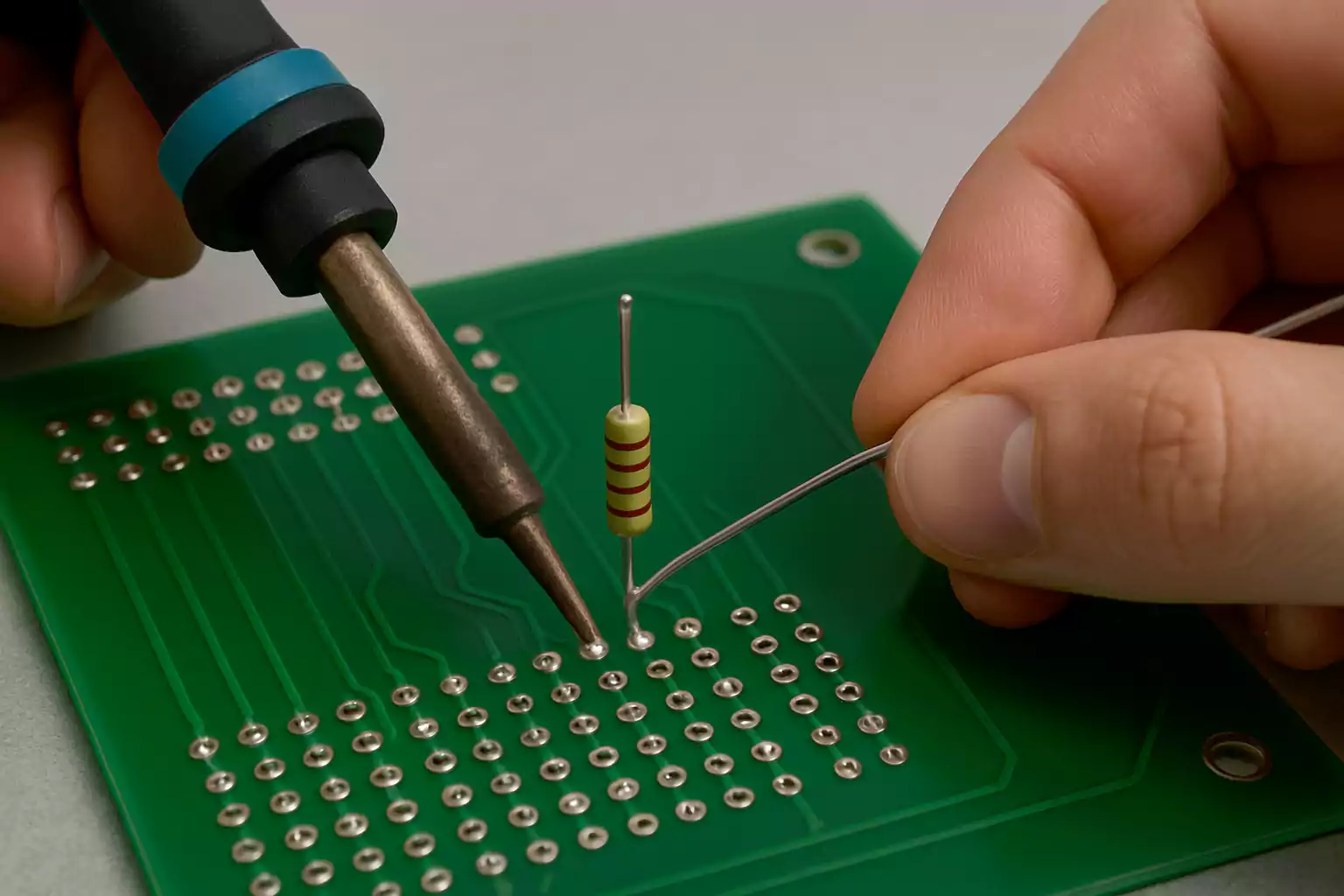
2. Insert and Secure Components
Gently insert the component leads into their respective holes:
- Push the component down until it sits flat against the PCB surface.
- Flip the PCB over, and use one of the following methods to secure the part:
- Slightly bend the leads outward to hold the component in place.
- Use masking tape or poster putty to temporarily fix parts.
- Consider using a PCB holder or “third hand” tool for added stability.
Well-secured components won’t shift during soldering, which helps prevent cold joints or misalignment.
3. Apply Flux (If Not Included in Your Solder)
Flux helps remove oxidation and promotes solder flow:
- Many solder wires come with rosin-core flux, but for oxidized surfaces or critical joints, applying additional liquid or gel flux can enhance results.
- Apply a small amount to the pad and lead using a brush or flux pen.
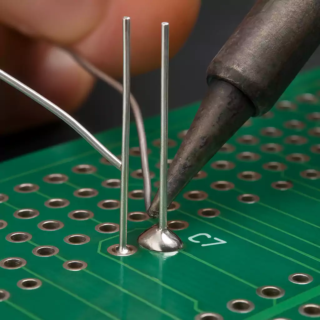
4. Heat the Joint Properly
This step is where most soldering issues originate, so technique matters:
- Place your soldering iron tip so it contacts both the component lead and PCB pad at the same time.
- Wait 1–2 seconds to let both surfaces reach soldering temperature.
- Feed solder into the joint—not the tip—so it melts and flows around the connection.
Let the solder flow naturally through capillary action into the plated through-hole.
5. Remove Solder Wire First, Then the Iron
When enough solder has flowed into the joint:
- Remove the solder wire first, then lift the iron tip from the joint.
- This sequencing helps prevent disturbed or "cold" joints.
The finished solder joint should look like a small, shiny volcano shape—smooth, concave, and slightly domed.
6. Trim Excess Leads
After soldering, flip the board and trim the extra component leads:
- Use flush cutters to snip the leads just above the solder joint.
- Be careful not to crush or stress the joint while cutting.
- Wear safety glasses—leads can snap off forcefully.
Clean lead trimming reduces the chance of shorts and improves board aesthetics.
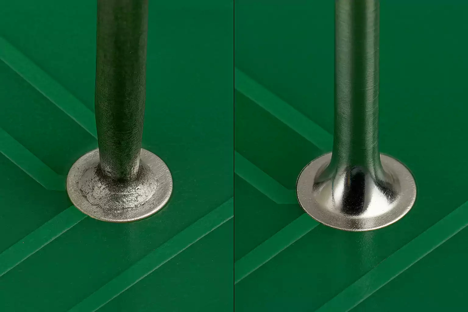
7. Inspect Your Work
Use a magnifier or inspection tool to check the quality of your solder joints:
- Good joints are shiny, smooth, and fully cover both the pad and lead.
- Bad joints may look dull, cracked, have holes (voids), or form "cold" blobs.
- Check for solder bridges, incomplete solder fill, or burned pads.
8. Clean Residual Flux
Some types of flux can be corrosive over time:
- Clean off residues with isopropyl alcohol (IPA) and a soft brush.
- Use a lint-free cloth or swab to gently remove the dissolved flux.
- Skip this step if you're using no-clean flux and appearance isn’t critical.
Performing each step with precision helps avoid common through-hole soldering issues like cold joints, lifted pads, or excess solder. Proper technique not only improves electrical performance but also boosts long-term durability and professional finish.
Common Mistakes, Troubleshooting & Fixes
Even with proper technique, through-hole soldering can go wrong. Here's how to identify and fix the most common problems:
1. Cold Joint
- Signs: Dull, grainy solder; weak or intermittent connection.
- Causes: Insufficient heat or movement before cooling.
- Fix: Reheat with fresh solder and proper tip contact.
2. Solder Bridge (Short)
- Signs: Solder unintentionally connects two pads or pins.
- Causes: Excess solder or lack of precision.
- Fix: Use solder wick or sucker to remove excess, then reflow.
3. Poor Wetting
- Signs: Solder beads up or doesn’t bond to pad/lead.
- Causes: Dirty or oxidized surfaces; not enough heat or flux.
- Fix: Clean with alcohol, apply flux, and reflow.
4. Excess Solder
- Signs: Large, blobby joints.
- Causes: Too much solder applied.
- Fix: Wick off the excess; apply less next time.
5. Lifted Pad
- Signs: Pad or trace lifts from the board.
- Causes: Overheating or pulling during rework.
- Fix: If functional, secure with epoxy or use a wire jumper.
Advanced Tips & Optimization Suggestions
Improve your through-hole soldering skills with these proven techniques for better quality and efficiency:
1. Anchor Multi-Pin Components First
When soldering connectors or pin headers, solder two diagonal pins first to hold the component in place. This prevents shifting and ensures alignment.
2. Use Proper Temperature Settings
Adjust soldering temperature based on your solder type:
- Lead-based: 320–350°C
- Lead-free: 360–400°C
Higher heat may be needed for large pads or ground planes.
3. Add Extra Flux for Tough Joints
Use liquid or gel flux on oxidized or large joints to improve wetting and flow. Even pre-fluxed solder can benefit from extra flux.
4. Pre-Tin Oxidized Component Leads
If using aged or salvaged parts, pre-tin the leads with fresh solder for better bonding and smoother joints.
5. Inspect with Magnification
Use a magnifier or microscope to check for cold joints, cracks, or bridges. Good inspection prevents rework later.
6. Keep Everything Clean
Regularly clean your soldering iron tip and PCB surface with isopropyl alcohol. Cleanliness directly affects solder joint quality
Frequently Asked Questions
Why isn't the solder sticking to the pad or pin?
This usually happens due to oxidation or contamination on the pad or lead. Clean all surfaces before soldering and ensure proper heat and flux are applied for good wetting.
How do I avoid solder bridges between pins?
Use a finer iron tip, apply solder sparingly, and use flux to control flow. Remove any bridges with solder wick or a desoldering pump.
What’s the ideal temperature for through-hole soldering?
·Lead-based solder: 315–350°C
·Lead-free solder: 350–380°C
Adjust based on board thickness and component size.
How do I remove a through-hole component safely?
Use a desoldering pump or solder wick with added flux. Avoid pulling components while solder is solid to prevent pad damage.
Why does my solder joint look dull or grainy?
This is likely a cold solder joint, caused by low heat or movement during cooling. Reheat the joint with flux until smooth and shiny.
How do I inspect if a through-hole joint is good?
Look for a shiny, concave fillet with good coverage of both the lead and pad. Use a continuity tester or magnification to verify.
Conclusion: Mastering Through-Hole Soldering
Through-hole soldering remains a fundamental skill for electronics prototyping and repair. By understanding the correct tools, techniques, and common mistakes, you can create reliable and long-lasting solder joints.
With practice, you’ll be able to:
- Set up an efficient soldering workspace
- Solder components with accuracy and consistency
- Identify and fix common soldering issues
For next steps, consider exploring related topics like SMD soldering, soldering standards, or PCB design tips to build on your foundation.