


When you design a circuit board, choosing the right switch can make a big difference in performance and safety.
One of the most common and practical switch types used in PCB projects is the Double Pole Single Throw (DPST) switch.
It may sound technical, but once you understand what “double pole” and “single throw” mean, it’s actually simple—and very useful.
In this guide, we’ll explain what a DPST switch is, how it works on a PCB, where to use it, and how to wire it correctly.
We’ll also show when a 12V DPDT automotive relay can be a better alternative for high-current or remote-controlled applications.
What Is a Single Throw Double Pole Switch (DPST) PCB?
A Double Pole Single Throw (DPST) switch controls two separate circuits at the same time with one action.
Each “pole” controls one circuit. When you flip the switch ON, both poles close; when you flip it OFF, both open.
Think of it as two independent switches that move together.
On a PCB, a DPST switch is usually mounted directly on the board or connected through soldered pins.
It’s a convenient way to turn on or off two sections of a circuit—like both positive and negative lines of a power input—at once.
Typical examples include:
- Turning on both the main power and a status light at the same time
- Cutting off both supply and ground lines for extra safety
- Controlling two separate loads with a single push or toggle action
Key Features of a DPST Switch
DPST switches are known for their simplicity and reliability. Here are the main features engineers appreciate:
- Two circuits, one action – Both poles switch together.
- Independent contacts – Each pole is isolated, preventing cross-talk between circuits.
- Simple ON/OFF operation – No complicated switching logic or states.
- Board-mountable design – Easy to integrate into PCB layouts.
- Variety of styles – Available as toggle, rocker, slide, pushbutton, or relay type.
This makes the DPST one of the easiest and most versatile switch types for PCB-based electronics.
Common Types of DPST Switches
DPST switches come in several shapes and mounting styles, depending on the project.
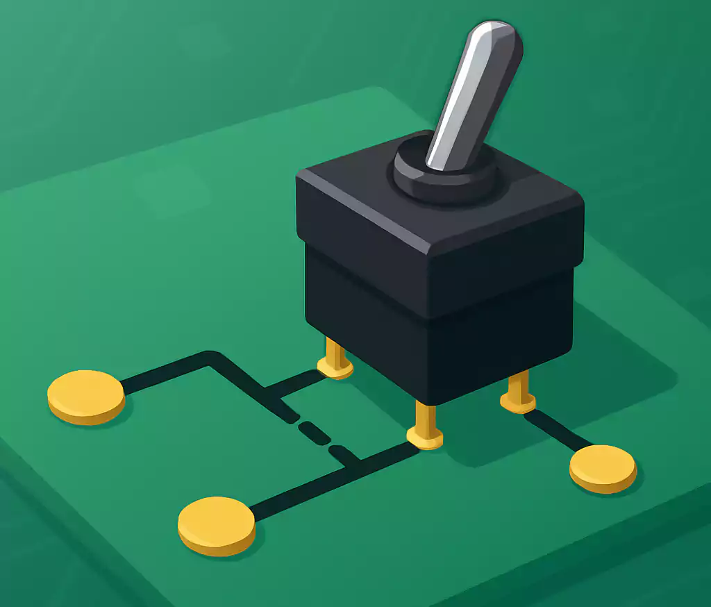
a) Toggle Switch
A small lever that you flip up or down.
It’s often used in control panels, lab instruments, and power supplies.
b) Rocker Switch
A flat switch that rocks back and forth.
Rocker DPSTs are popular in consumer products, lighting equipment, and power strips.
c) Slide Switch
A small sliding actuator that moves horizontally.
Common in compact or handheld devices.
d) Relay-Type DPST
Some PCB relays use a DPST contact arrangement.
Instead of manual operation, they’re activated by a coil—perfect for automated or MCU-controlled systems.
Most DPST switches for PCBs use through-hole (THT) mounting, which gives a solid mechanical bond and good current capacity.
Typical Applications of DPST Switches
DPST switches are used anywhere two circuits need to be turned on or off together.
Here are some common use cases you’ll find on modern PCBs:
- Main Power Control – Many designs use DPST switches as master power switches.
When flipped OFF, both live and neutral (or positive and ground) lines disconnect—safer than a single-pole switch. - Dual-Function Circuits – One pole powers a load, while the other controls an indicator LED, a fan, or a secondary circuit.
- Test and Debug Boards – Engineers use DPST switches to isolate test circuits from the main supply during troubleshooting.
- Automotive and Industrial Equipment – DPST switches are ideal for 12V systems where both sides of a load must disconnect completely when the engine or power system is off.
Because DPST switches can handle two isolated circuits, they’re often used in power entry modules, audio gear, battery management systems, and automation controllers.
How a DPST Switch Works on a PCB
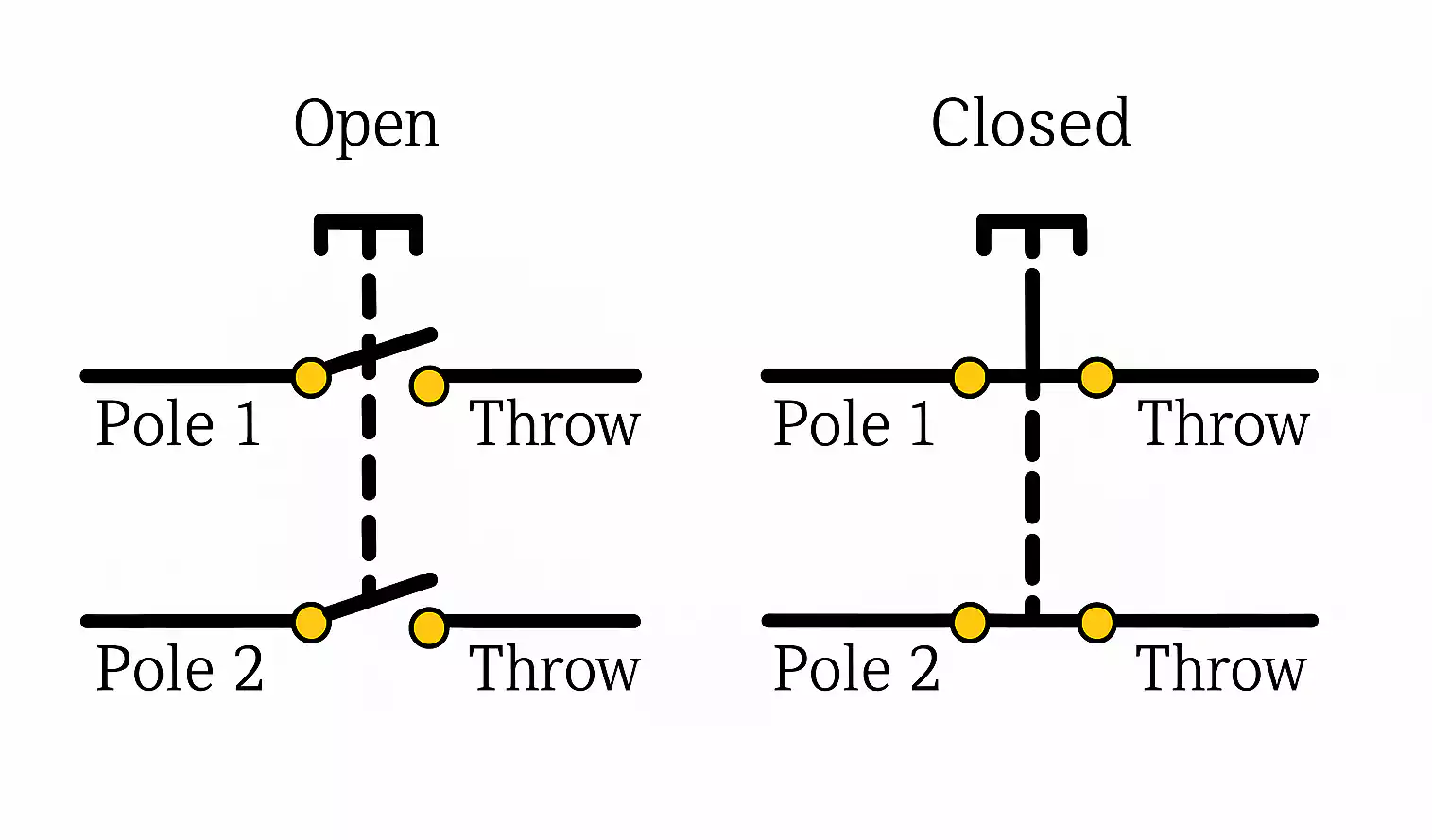
Each DPST switch has four terminals—two for each pole.
Internally, there are two sets of contacts that open or close together.
When the switch is ON, both sets of contacts are closed, connecting each pair of terminals and allowing current to flow through both circuits.
When the switch is OFF, the contacts open, breaking both circuits at once.
On a PCB, each pole connects to its own trace. Designers usually route these traces separately to maintain isolation.
Both poles share a single actuator (the lever or rocker), so they move in perfect sync.
This simple mechanism ensures two-circuit control without complex wiring or microcontrollers.
How to Choose the Right DPST for Your PCB Project
Selecting a DPST switch is easy if you focus on the key points below.
Step 1: Check Voltage and Current Ratings
Always pick a switch rated higher than your circuit’s maximum voltage and current.
For example, if your design uses 12V DC at 2A, a switch rated for 24V 5A will work safely.
Step 2: Match Mounting Style and Size
Look at your PCB layout.
Is there space for a through-hole switch, or do you need a smaller, panel-mounted type wired?
Fast Turn PCBs can adjust pad sizes and hole diameters during manufacturing to fit your chosen switch.
Step 3: Consider the Operating Environment
For automotive or outdoor systems, choose a DPST switch that’s sealed against dust and moisture (IP-rated).
For industrial systems, look for flame-retardant materials and mechanical endurance specs.
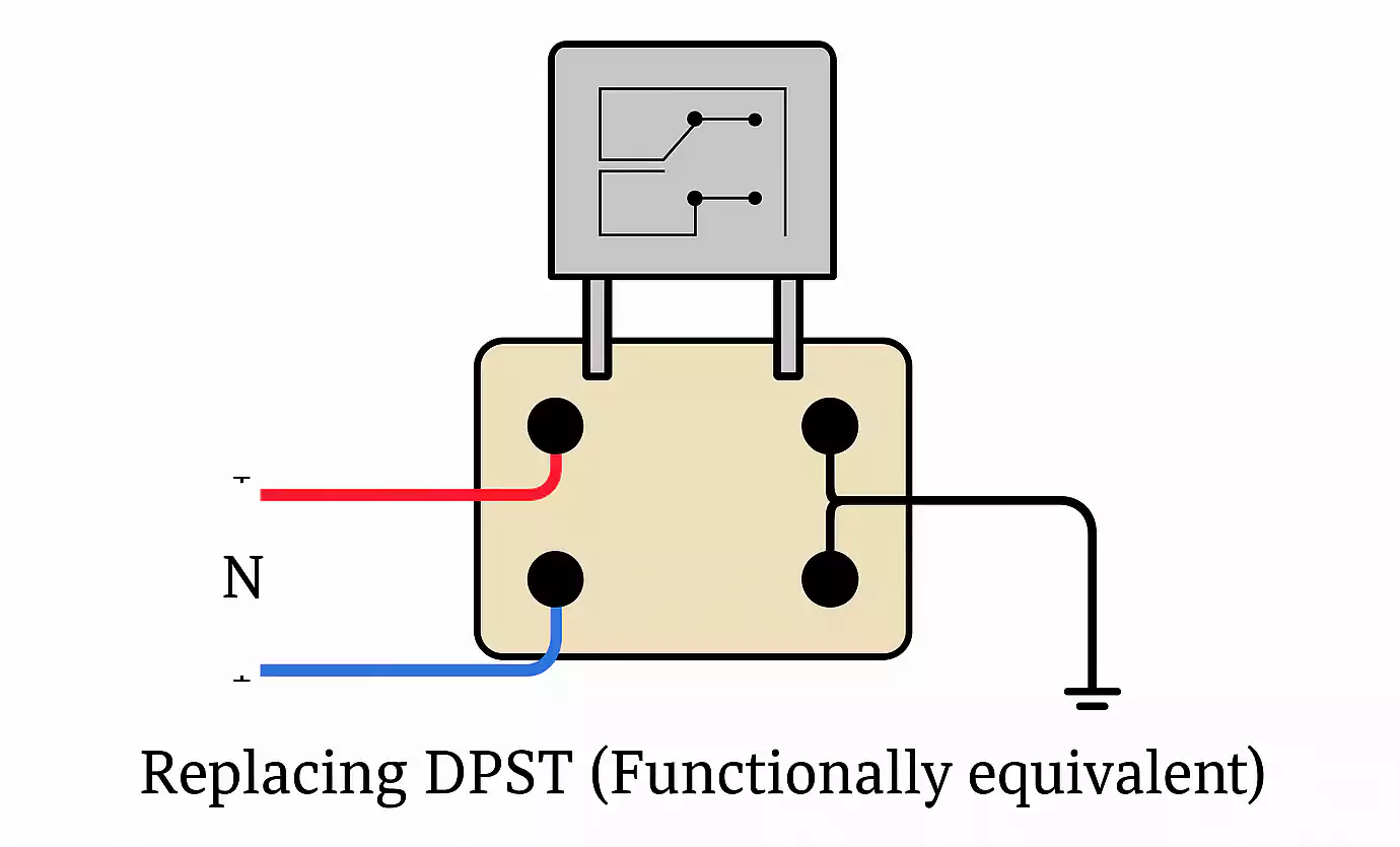
If your project needs remote or automatic switching, consider replacing the manual DPST with a 12V DPDT relay that mounts directly on the PCB.
A relay can handle higher currents and can be driven by a microcontroller or control circuit.
Wiring and Example Diagrams for DPST on PCB
Let’s go through two easy wiring examples.
Example 1: Dual Power Cut-Off
Use the DPST switch to break both the positive and negative lines.
When the switch is ON, both lines connect; when OFF, both are isolated.
This method provides extra safety and prevents leakage or standby current.
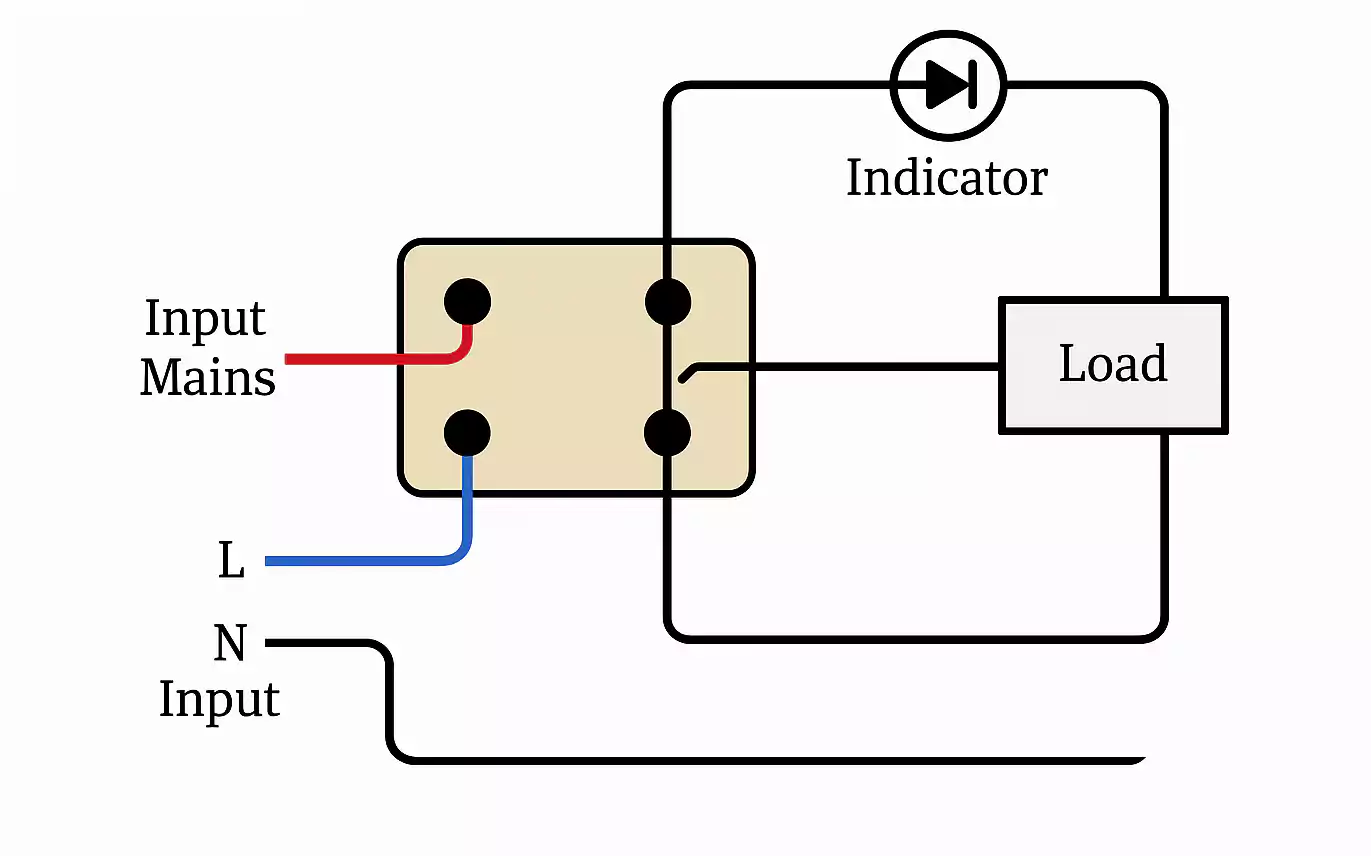
Example 2: Load + Indicator
Use one pole to power your main load (e.g., a motor or heater), and the other to control an LED indicator.
When the switch is ON, the load operates, and the LED lights up.
When OFF, both are disconnected.
In PCB design, keep high-current traces wide and separate from low-voltage control traces.
If your circuit drives inductive loads, add a flyback diode or RC snubber to protect the contacts from voltage spikes.
DPST vs. DPDT vs. SPDT — What’s the Difference?
Understanding switch terminology can be confusing at first, but here’s an easy way to remember it.
| SPDT | 1 | 2 | Select between two outputs (A or B) |
| DPST | 2 | 1 | Turn two circuits ON/OFF together |
| DPDT | 2 | 2 | Reverse polarity or switch two loads between two sources |
In short:
- SPDT: One circuit, two paths—used for signal routing or selection.
- DPST: Two circuits, one action—used for main power switching.
- DPDT: Two circuits, two actions—used when both circuits need to reverse or swap connections, such as motor direction control.
A DPDT switch can also act as a DPST by using only one throw. Just leave the unused terminals unconnected.
When to Use a 12V DPDT Relay Instead
In many automotive or industrial PCBs, a mechanical switch isn’t the best option.
If you need to switch large currents, remote signals, or automated control, a 12V DPDT relay can do the same job more efficiently.
Here’s why:
- It isolates the control circuit from the power circuit.
- The relay coil can be triggered by a microcontroller, transistor, or logic signal.
- It handles higher loads (10–30A, common in automotive relays).
- It’s compact and fits easily into a PCB layout.
In this setup, the DPDT relay effectively performs the same function as a DPST switch—both poles switch together.
But the control is electronic, not manual.
FAQs
1. Is there a Double Pole Single Throw (DPST) switch?
Yes. A DPST switch has two independent circuits controlled by one actuator. It’s widely used for main power ON/OFF applications.
2. Can a DPDT switch be used as a SPDT?
Yes. Simply use one side of the DPDT switch. Leave the other side unconnected.
3. Can I use a double-pole switch for a single circuit?
Yes, you can. You may connect only one pole and leave the second pole unused.
4. What’s the difference between SPDT and DPDT?
SPDT controls one circuit with two outputs; DPDT controls two circuits with two outputs each—essentially two SPDT switches in one body.
5. When should I use a relay instead of a switch?
Use a relay when your circuit needs high-current control, electrical isolation, or remote operation via a low-power signal (e.g., an MCU).
6. How does a DP switch work?
A double-pole switch has two sets of contacts that open and close together, allowing you to control two separate circuits with a single action.
Final Thoughts
The Double Pole Single Throw (DPST) switch is one of the simplest and safest ways to control two circuits on a PCB.
Its dual-circuit control helps engineers design boards that power on and off cleanly without cross-connection or leakage.
If you’re designing a PCB for power distribution, lighting, audio, or automotive electronics, adding a DPST switch can make your circuit more reliable and user-friendly.
And if you need higher current or automated control, a 12V DPDT relay is an excellent upgrade.
At Fast Turn PCBs, we help engineers design and build reliable boards with the right component footprints, safe trace spacing, and quick production turnaround.
