Why You need to understand short circuits
It's 2 a.m. and the room is quiet—until a muted pop from the wall outlet throws the house into darkness and the acrid smell of burning insulation fills the air. What happened wasn't an overload or a lightning strike; it was a short circuit—electricity's way of taking an unauthorized shortcut. In the seconds it took for the breaker to trip, the copper conductors behind your drywall reached temperatures hot enough to vaporize metal and ignite framing lumber.
If that sounds dramatic, consider the numbers. U.S. fire departments still tackle roughly 24,000 residential electrical fires every year, a burden that claimed 310 lives and inflicted $871 million in property damage in the most recent three-year NFIRS analysis. Updated 2025 figures show the human toll barely improving: 295 deaths, 900 injuries and more than $1.2 billion in losses in a single year.
Short circuits are not a fringe contributor—they're the prime suspects. When investigators pinpoint ignition sources, 34 percent of residential electrical fires trace back to short-circuit arcing (23 percent "unspecified arcs" plus 11 percent from worn insulation). In other words, one out of every three electrical-fire call-outs begins with a conductor that let current jump across an unintended path.
The impact isn't limited to homes. In industrial settings, a single short-circuit flash can halt production lines, trigger data-center blackouts, and light up balance sheets. A 2024 Siemens study put the cost of unscheduled downtime at 11 percent of annual revenue for the world's 500 largest manufacturers—about $1.4 trillion—with some plants losing $2.3 million per hour of silence. For businesses running on tight supply chains and just-in-time logistics, one stray arc is the difference between profit and hemorrhage.
Yet despite the stakes, short circuits remain misunderstood. Many homeowners lump them in with overloads; DIY tinkerers assume modern breakers make them a non-issue; facilities teams schedule maintenance around everything except prospective fault current. This guide exists to flip that script. By the time you reach the FAQ at the end, you'll know:
- What a short circuit really is (and isn't)
- Why it cripples everything from phone chargers to sub-stations
- How to spot early warning signs before wires glow incandescent
- Which protection devices, calculations and standards actually work
Master these fundamentals, and you're not just preventing nuisance trips—you're safeguarding lives, property and entire production schedules. Let's get started.
What is a short circuit?
1. The one-sentence definition
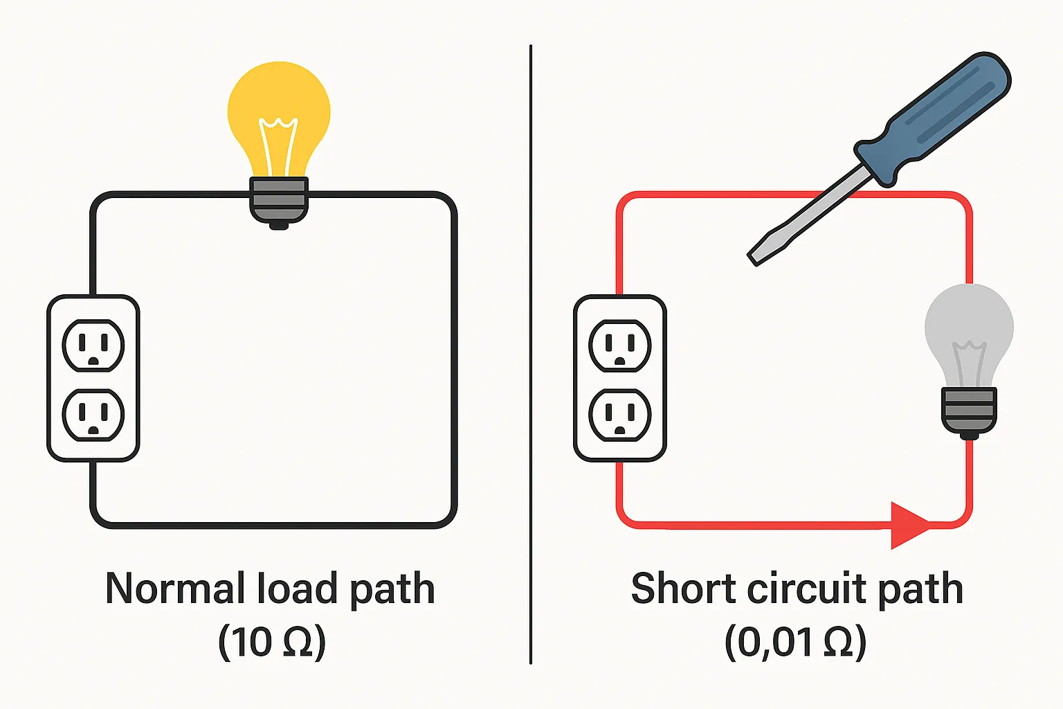
A short circuit occurs when electricity finds an unintended very-low-resistance path between two points at different voltages, so the current bypasses the normal load and surges virtually unchecked.
2. Why it's explosive
Ohm's law says I = V/R. Keep the supply at 120V but let R collapse from 10Ω (typical household load) to 0.01 Ω (a copper screwdriver bridging hot-to-neutral) and the current skyrockets from 12A to 12,000A—1,000 × more. Even though the resistance is tiny, heating is proportional to I²R, so you still dump 1.4 MW of heat into that screwdriver in milliseconds, hot enough to vaporize metal and launch an arc plasma > 5,000°C.
3. Don't confuse it with its cousins
| Fault | What touches what | Main danger | Typical protective device |
|---|---|---|---|
| Short circuit | Hot ↔ Neutral (or phase-to-phase) | Fire, equipment blow-up | Standard breaker (magnetic trip) |
| Ground fault | Hot ↔ Ground | Electric shock | GFCI interrupter |
| Overload | Too many loads on one circuit | Conductor overheating over minutes | Thermal breaker element |
| Arc fault | Intermittent sparking across a gap | Hidden wiring fires | AFCI breaker |
Ground faults and arc faults are both forms of short-circuit behavior, but their current paths and detection methods differ, which is why the NEC mandates GFCI and AFCI devices in addition to ordinary breakers.
4. Quick taxonomy
Engineers label shorts by where they happen: line-to-neutral, line-to-ground, phase-to-phase, or series faults. You'll meet each of these in the next section, along with the real-world scenarios that create them.
The full spectrum of short-circuit types
Engineers classify short circuits by where the unintended connection occurs, how many conductors are involved, and whether the fault current is balanced across phases. Knowing the subtleties is essential: it tells you which devices (breaker, GFCI, AFCI, relay) will respond first and how much thermal-mechanical punishment your conductors must endure.
1. Line-to-Neutral (L-N) — the "household" parallel short
A hot conductor touches neutral, bypassing the load. Because the fault sits across the full secondary voltage of a transformer, its current can be ~1.5 × higher than a line-to-line fault at the same point.
- Typical context: Loose wire in a receptacle or a metal tool bridging terminals.
- Protective priority: Instantaneous (magnetic) trip on the branch-circuit breaker, backed by fuse or MCCB upstream.
- Hazard focus: Thermal runaway → copper vapor arc → panel fire.
2. Line-to-Ground (L-G) — the classic ground fault
Here the hot conductor contacts a grounded surface or equipment case, sending current literally "to earth." Shock risk trumps fire risk. GFCI devices detect the 5–6 mA imbalance long before over-current devices would react.
3. Line-to-Line (Phase-to-Phase, L-L)
Two live conductors of different phases touch—common on windy overhead lines that whip together. Fault current is limited by the source impedance of both phases, so it is lower than a three-phase bolted fault but still high enough to destroy bus bars in milliseconds.
4. Three-Phase Symmetrical (L-L-L or L-L-L-G)
All three phases short together, with or without ground involvement. Though only ~2–5 % of real-world faults, this is the scenario switch-gear designers use to size interrupting ratings because it produces the absolute maximum prospective fault current.
5. Unsymmetrical multi-line faults
Most real faults are unbalanced:
- Single L-G (~70–80 % incidence)
- L-L-G (two phases + ground)
- Double-L open conductor + ground
The asymmetry means phase currents differ in magnitude and angle, so protective relays use negative- and zero-sequence components to detect them.
6. Series faults (a.k.a. open-circuit or "series short")
Counter-intuitively, not every dangerous fault is high-current. A series fault is a cracked conductor or loose terminal that inserts extra resistance. Current may stay below breaker thresholds, but the tiny contact area forces that current through a pin-point, generating localized arcs ≥ 3 000 °C that ignite insulation. IEC and NEC therefore mandate AFCI breakers in dwelling circuits to sense the high-frequency arc signature.
7. Bolted vs. arcing faults
"Bolted" (a screwdriver wedged across bus bars) means near-zero impedance → peak current. "Arcing" implies a plasma gap whose resistance rises as it heats, producing lower steady-state amperes but far higher radiated heat and pressure. Protection studies model both, then apply the worst-case of each to equipment ratings and PPE selection.
Quick reference
| Fault label | Conductors involved | Current balance | Primary danger | First-line protection |
|---|---|---|---|---|
| L-N | 1 hot → Neutral | Unsymmetrical | Fire / equipment blow-up | Magnetic breaker |
| L-G | 1 hot → Ground | Unsymmetrical | Electric shock | GFCI |
| L-L | 2 hots | Unsymmetrical | Arc flash, fire | Instantaneous OCPD |
| L-L-L / L-L-L-G | 3 hots (balanced) | Symmetrical | Max fault current | High-rupture capacity breaker |
| L-G, L-L-G, etc. | 1–2 hots + Ground | Unsymmetrical | Mixed (shock + arc) | Sequence-sensing relay + breaker |
| Series (open) | Single conductor crack | N/A | High-temperature arcing | AFCI |
Understanding which bucket a fault sits in lets you pick the right interrupter curve, set relay pickup, and calculate incident energy with confidence—and that’s the foundation for the calculation and protection sections that follow.
Digging into the causes
More than 90 % of real-world short circuits trace back to just seven root causes. Master these and you eliminate most of the risk before you ever start calculating fault levels.
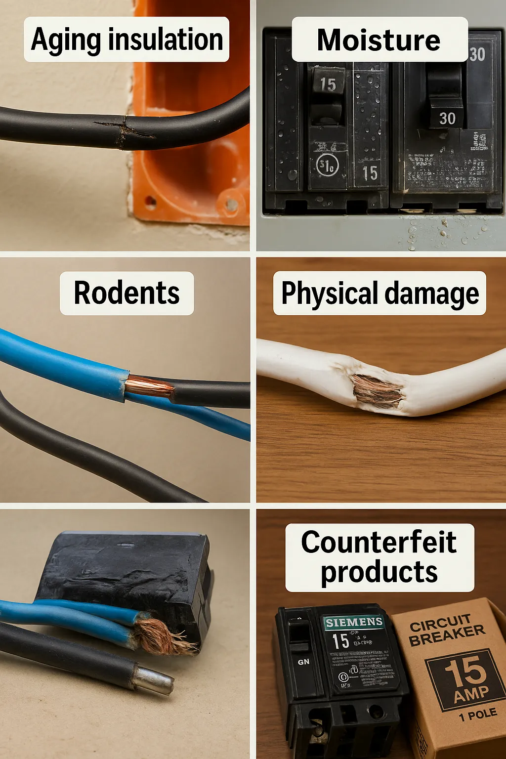
1. Aging insulation & thermal stress
Polyvinyl chloride (PVC) and rubber sheaths dry out, crack, and oxidise after decades of heat cycles. NFPA data show deteriorated wiring/insulation is implicated in 5 % of all U.S. home structure fires and 4% of related deaths—a non-trivial slice of 46,500 yearly incidents.Visual red flags include brittle jackets, discoloration around terminations, and a “hair-line” pattern on cable bends.
Preventive moves: load-balancing to reduce conductor temperature, IR thermography on panels, and NEC-70 Art. 210.12 AFCI retrofits in circuits older than 40 years.
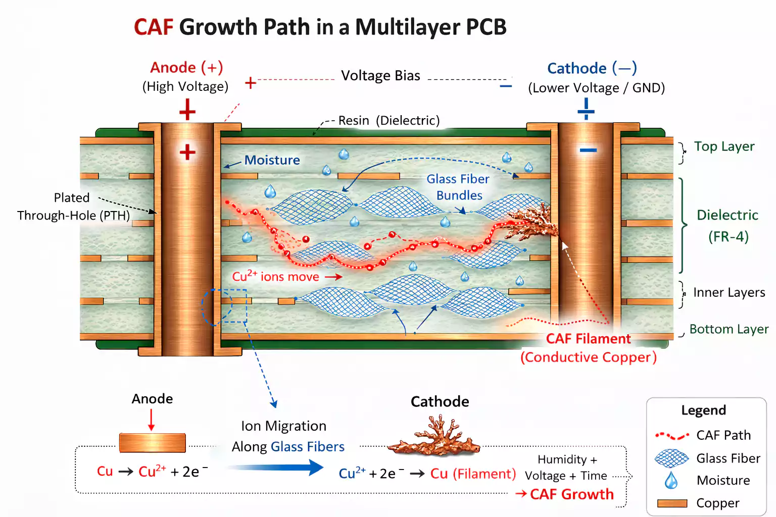
2. Moisture ingress & condensation
Water is a conductor once it dissolves mineral ions. High-humidity enclosures form micro-layers of condensation on PCBs; ionic tracks then bridge traces and drop insulation resistance until a short develops. Case studies on pump-room drives found relative-humidity spikes created 100% RH locally, initiating PCB shorts.
Seal entry glands, add space heaters or desiccant breathers, and maintain dew-point at least 5 °C below enclosure temperature.
3. Conductive dust, metal shavings & corrosion products
Fine metal dust, carbonised fibres, or weld spatter can settle across live busbars. G&W Electric's 2024 arc-flash review lists dust accumulation as a leading ignition source, especially when mixed with humidity that lowers surface resistance.
In machining lines, aluminium shavings inside VFD cabinets have paralysed production and melted filter capacitors. Housekeeping, NEMA-12/4X enclosures, and periodic compressed-air purges are your first defence; fit HEPA intake filters where metal dust is unavoidable.
4. Rodent & pest damage
Rats, mice and squirrels gnaw constantly to trim their incisors, stripping insulation right down to bare copper. Rodents are blamed for 20 – 25% of "fires of unknown origin", translating to roughly 15,000–30,000 U.S. house fires per year.
Exposed conductors arc against framing or each other, lighting nest material like tinder. Install metal conduit in attics, seal cable penetrations, and deploy ultrasonic deterrents where food storage attracts pests.
5. Mechanical abuse, vibration & bending fatigue
Cable jackets chafe on steel conduits, forklifts crush festoon loops, and repetitive robot motion exceeds bend radii. Abrasion alone punches through insulation, setting the stage for parallel or series shorts.
Best practice is generous radius guides, strain-relief grips, and vibration-resistant ferrules; in high-flex chains, downgrade to finely-stranded class 5 conductors rated for ≥ 10 million cycles.
6. Sub-standard or counterfeit components
Knock-off breakers, receptacles or power strips often omit arc-quenching alloys and thermal trips. Eaton's forensic bulletin warns that counterfeit electrical gear can overheat or short, costing the industry $600 billion globally.
Customs'"Operation Short Circuit" seized 1 million fake electrical items in just three months, many with zero compliance testing. Buy only from authorised distributors, verify UL/CE markings, and use QR-code authentication tools where available.
7. Poor workmanship & loose connections
Undertorqued lugs, non-standard cable joints, and nicked conductors create high-resistance hot spots. A 2024 root-cause study shows loose or non-standard joints are far more likely to initiate short circuits than properly crimped terminations.
Even a 0.1 Ω contact drop at 100 A wastes 1 kW as heat—enough to anneal copper, soften insulation, and arc across phases. Thermal imaging during load, periodic torque checks, and crimp-force loggers (per IEC 61238-1) are your cheapest life-insurance.
Hazards & Consequences
When a breaker snaps open you've witnessed the best-case scenario. Had the fault persisted for even a few extra cycles, the chain-reaction below could have unfolded.
1. Thermo-mechanical destruction
A bolted short forces current to rise by three–four orders of magnitude; the I²R energy released in ½ cycle is enough to liquefy copper and steel. The plasma column of an arc flash routinely exceeds 20 000 °C—over three times the surface of the sun—while sound pressure spikes near 160 dB, rivaling a gunshot.
As copper vaporizes it expands ≈ 67 000× by volume, producing an internal blast that can rip switchgear doors from their hinges.
2. Arc-flash & blast injuries
The thermal/pressure wave is not just hot—it is deadly. Johns Hopkins modeling of OSHA data suggests ~630 arc-flash injuries still occur annually in U.S. workplaces. Survivors often suffer third-degree burns, tympanic-membrane rupture, or shrapnel wounds from vaporized bus-bar droplets.
3. Electric shock lethality
Contact currents as low as 30 mA can induce ventricular fibrillation in < 50 ms. Ground-fault paths created by insulation failure or moisture bridge the fault to chassis metal, exposing anyone nearby. The Bureau of Labor Statistics counted 3 260 non-fatal electrical injuries with days lost from work in 2021-22 alone.
4. Fire ignition & structural loss
A short-circuit arc is essentially an internal blow-torch. NFPA trend data show that electrical distribution or lighting equipment ignites an average 31 647 U.S. home structure fires per year, killing 425 people and causing US $1.6 billion in direct losses. Wiring itself accounts for 4% of all home fires but 6% of the deaths.
5. Asset damage & digital blackouts
One millisecond of fault can imprint permanent electro-migration voids on silicon, roast transformer insulation, and pit breaker contacts beyond reuse. In the digital economy the knock-on costs are brutal:
- 20% of data-center outages now cost over US $1 million to remediate.
- 93% of mid-size and large enterprises say a single lost hour exceeds US $300 000; 41% peg it between US $1 – 5 million per hour.
Add SLA penalties, compliance fines, and brand damage and you have a balance-sheet event, not just a maintenance ticket.
6. Secondary ripple effects
- Toxic smoke & corrosive residues from PVC insulation can render control rooms inoperable for weeks.
- Water intrusion from fire-suppression or firefighting often outstrips the direct electrical damage.
- Regulatory exposure rises sharply: OSHA's 2024 guidance aligns with NFPA 70E, requiring documented incident-energy analysis and PPE or risk citations and stop-work orders.
Bottom line: a short circuit unleashes thermal, mechanical, and economic forces that dwarf the simple "lights-out" moment you see at the panel. Treat every breaker trip as a forensic clue, not an annoyance—the real hazard is everything that almost happened.
Basic calculation
1. The equivalent-impedance method (IEC 60909 "one-line" rule)
For low-voltage systems you can treat everything upstream of the fault—the service transformer plus the phase- and neutral-conductor run—as a single complex impedance Z<sub>Σ</sub>.
IEC 60909 expresses the initial symmetrical short-circuit current as
Ik′′=c Un3 ZΣI''_{k}=\frac{c\;U_{n}}{\sqrt{3}\;Z_{Σ}}Ik′′=3ZΣcUn
- U<sub>n</sub> = rated line-to-line voltage
- c = voltage factor (typically 1.05 for LV networks)
- Z<sub>Σ</sub> = Z<sub>transformer</sub> + Z<sub>cable</sub> (+ Z<sub>utility</sub> if given)
In single-phase 120 V branch circuits the same concept collapses to Ohm's Law:
IPFC=VphaseZΣI_{PFC}=\frac{V_{phase}}{Z_{Σ}}IPFC=ZΣVphase
where Z<sub>Σ</sub> is now simply the transformer secondary impedance plus the round-trip conductor resistance (reactance is negligible at these lengths).
2. A worked example (typical US home)
| Step | Calculation | Result |
|---|---|---|
| 1. Source data | 25 kVA, 120/240 V pole transformer, %Z = 2.5% (manufacturer name-plate) | — |
| 2. Transform %Z to Ω | Zxfmr=0.025×VLL2S=0.025×240225000Z_\text{xfmr}=0.025\times\frac{V_{LL}^{2}}{S}=0.025\times\frac{240^{2}}{25 000}Zxfmr=0.025×SVLL2=0.025×250002402 | 0.0576 Ω |
| 3. Conductor loop R | 6 AWG Cu, 30 m one-way → 60 m loop. 6 AWG ≈ 0.403 Ω/1000 ft = 0.00132 Ω/m → 0.00132×600.00132 × 600.00132×60 | 0.0237 Ω |
| 4. Total Z<sub>Σ</sub> | 0.0576 Ω + 0.0237 Ω | 0.081 Ω |
| 5. Prospective fault current | 120 V leg-to-neutral: 120/0.081120/0.081120/0.081 A 240 V leg-to-leg: 240/0.081240/0.081240/0.081 A | ≈ 1.5 kA (L-N)≈ 3.0 kA (L-L) |
Those numbers tell you the branch breaker must have an interrupting rating ≥ 3 kA and the service disconnect ≥ the upstream utility value. NEC 110.9 demands that every over-current device be at least equal to the available fault current at its line terminals.
Reality check: a 2–4 % pole transformer only 15 m away often yields 5–10 kA at the service, so always verify utility data before finalising breaker and bus ratings.
3. Quick-test tools & field shortcuts
- A loop-impedance tester or multifunction meter will display I<sub>pf</sub> directly by injecting a calibrated pulse—ideal when conductor lengths or utility X/R values are unknown.
- BS 7671 and NEC alike require the prospective fault current (or earth-fault current) to be measured, calculated or otherwise determined at "every relevant point" before energising a new installation.
- Keep the worst-case (highest) result on the panel schedule; that single figure anchors PPE arc-flash calculations and dictates the minimum kAIC rating for every device downstream.
4. Your take-away assets
- IEC 60909 cheat-sheet – ready-reference of c-factors, X/R ratios and typical transformer %Z.
- Excel / Google-Sheet calculator – enter transformer kVA & %Z, conductor gauge & run length, and it autocalculates PFC at each node—perfect lead magnet.
- Loop-impedance test log template – document field readings to prove NEC 110.9 / BS 7671 compliance.
Master these three approaches—formal IEC math, a back-of-the-napkin Ohm's-law check, and an on-site tester reading—and you can size breakers, spec busbars and sign off inspection certificates with confidence.
Protection architecture
1. Pick the right protective devices and time-current curves
| Device | How it trips | Typical pickup / curve | Where it shines | Key spec to watch |
|---|---|---|---|---|
| Time-delay fuse (UL Class RK5) | Single-use metal link melts; current-limiting | Opens in ≤ 0.01 s at 10× In; dual-element design lets 500 % motor inrush ride through | Motor feeders, UPS bypass lines | kAIC rating (up to 300 kA at 600 V) |
| MCB (IEC 60898) | Thermal + magnetic | Curve B 3–5 In, C 5–10 In, D 10–20 In | B: domestic; C: mixed commercial loads; D: high-inrush motors | Select curve so load peak < 0.8 × trip band |
| MCCB (IEC 60947-2) | Electronic long-time, short-time & instantaneous | Ir adjustable 1.05–1.2 In; Isd 1.5–10 Ir | Feeders/service entrances up to 1600 A | Fine-tune Isd to sit just below downstream device I<sub>k</sub> |
| GFCI (UL 943 class A) | Senses 4–6 mA imbalance to ground | Trips within 25 ms | Wet areas, tools, EV chargers | Ensure 6 mA max trip per UL 943 §1.2 |
| AFCI (NEC 210.12) | Detects high-frequency arc signatures | < 1 s once arcing pattern confirmed | Dwelling and hotel guest rooms, now most 125 V 15/20 A branch circuits | Listed "combination-type" devices protect entire circuit |
Design tip: coordinate curves "from the load upstream" so each downstream device clears faults before its upstream backup (selective coordination). NEC 240.1–240.12 requires that the over-current device's interrupt rating meet or exceed the available fault current at its line terminals.
2. Design standards & conductor sizing
Code anchors
- NEC 240 – over-current protection; sets rules for breaker/fuse ampere rating and short-circuit current rating (SCCR).
- NEC 250 – grounding & bonding to ensure a low-impedance path that lets the device above operate fast.
- IEC 60364-5-52 – European design guide; Tables give admissible currents versus conductor cross-section, installation method and temperature.
Conductor ampacity & adiabatic limit
- Use NEC Table 310.16 (60 °C/75 °C/90 °C columns) or IEC tables, then derate for >3 current-carrying conductors, ambient >30 °C, or >50 °C for rooftop raceways.
- Confirm that I²t let-through of the chosen device is ≤ k S² (adiabatic equation) so the conductor survives the worst fault.
Interrupting & SCCR sizing shorthand
- Breaker kAIC ≥ prospective fault current at its line terminals (calculated in Section 6).
- Service equipment often needs 25–65 kA ratings even in small commercial buildings; check utility data sheets.
3. Preventive maintenance – keep protection alive
| Routine | Standard / best practice | Interval | What you’re looking for |
|---|---|---|---|
| Infrared thermography | NFPA 70B-2023 makes IR scans mandatory on all electrical equipment every 12 months; Condition 3 gear every 6 months. | 6–12 mo | >10 °C rise at terminations or breaker poles signals loose lugs or overloads. |
| Insulation-resistance test | IEEE 43 recommends 1 MΩ + 1 MΩ per kV as a baseline (correct to 40 °C). | Annually or after repairs | Trending drop >50 % year-on-year indicates moisture or insulation breakdown. |
| Breaker secondary-injection / trip testing | Manufacturer specs | 3–5 yr (MCB) / 1–3 yr (MCCB/ACB) | Verify long-time & instantaneous pickups match dial values; update settings after load changes. |
| Torque & visual inspection | NEC 110.14 & OEM tables | 1 yr | 20 % of breaker failures trace to undertorqued lugs—check with a calibrated wrench. |
A disciplined maintenance loop closes the protection ecosystem: design the right device, set it to the right curve, install it on the right conductor, then prove regularly that nothing has drifted. Follow that cycle and the protective system you build today will still clear faults safely a decade from now.
Troubleshooting & Repair
1. A six-step field workflow
Prerequisite: follow NFPA 70E's "electrically safe work condition" sequence—identify all power sources, open the disconnecting means, verify absence of voltage, and apply personal lockout/tagout (LOTO) devices before you touch a conductor. OSHA 1910.333 makes those practices a legal obligation in the U.S.
Kill power at the highest upstream device
Throw the main breaker or service disconnect—not just the branch breaker you think is bad. This guarantees you're not relying on a potentially welded contact.
Prove‐dead, then test your tester
Use a multimeter or two-pole tester: live source → circuit under test → live source again. That double-check catches a dead battery or blown meter fuse.
Isolate the culprit branch
With the main still off, switch all branch breakers to off. Re-energize the main and close breakers one at a time. The one that instant-trips contains the fault.
Divide-and-conquer diagnostics
- Disconnect every load (plugs, fixtures) on that branch.
- Measure resistance L-N and L-G at the panel. A reading < 2 Ω means a hard short.
- Still low? Open the first junction box and split the circuit in half; test each half and keep bisecting until the low reading disappears. This “binary search” cuts tracing time dramatically.
Repair or replace
Common fixes include: tightening a loose neutral bus screw, stripping back scorched insulation and splicing with an insulated butt crimp, replacing a nicked cable run, or swapping a burned receptacle. Use listed wirenuts or ferrules; never "back-stab" twice on the same hole.
Re-verify & re-energize
Insulation resistance ≥ 1 MΩ (corrected to 40 °C) passes IEEE 43 guidance; loop-impedance should match—or be lower than—values used in your fault-current study from Section 6. Re-energize, log breaker thermal rise with an IR camera after 10 min, and record results for compliance files.
2. Red-line situations—call a licensed electrician
- The fault is ahead of the main breaker or inside the service meter pan.
- Repeated trips persist after you've replaced obvious damaged parts.
- Aluminum branch wiring, knob-and-tube, or mixed Cu/Al splices are present.
- You must alter service equipment or feeder conductors—NEC 110.17 (2023) now requires those tasks be done by "qualified persons trained in the servicing and maintenance of electrical equipment."
- Local code mandates inspection for any new breaker, panel, or circuit extension.
3. Top DIY booby-traps to sidestep
- Skipping lockout—shutting a breaker without tagging it violates OSHA and runs the risk of someone else switching it back on.
- Trusting a non-contact voltage pen alone—they miss open neutrals and phantom voltages.
- Making terminations outside a box—open splices invite shorts and are illegal under every version of the NEC.
- Cutting conductors too short—less than 75 mm (3 in) in the box leaves no slack for solid connections.
- Back-stabbing receptacles—spring clamps loosen under heat/vibration; side-screw or Wago-style lever clamps hold torque.
- Oversizing fuses/breakers "to stop nuisance trips"—a Family Handyman review lists this as a leading homeowner error that leads directly to fire.
Follow this checklist methodically and you'll not only clear the immediate short but also document code-compliant work that stands up to inspection—and, most importantly, prevents the same fault from making an encore appearance.
FAQs
Does a short circuit always make sparks or a loud pop?
Not necessarily. Sparks are common when metal contacts separate in air, but a "bolted" fault (tight metal-to-metal contact) can pull tens of kilo-amps with no visible flash until the conductor fails. Your first clue may simply be a breaker trip or a dark screen.
Why does my breaker trip the instant I reset it?
Modern molded-case breakers have an instantaneous magnetic element that reacts in <1 electrical cycle (≈ 16 ms at 60 Hz) once current exceeds about 10× the breaker's rating. This prevents the copper bus from vaporising.An immediate re-trip therefore points to a true short, not a slow overload.
What’s the difference between a short circuit and a ground fault?
Short circuit = hot-to-neutral (or hot-to-hot) path; current bypasses the load. Ground fault = hot conductor touches a grounded surface; main danger is electric shock. They share symptoms (tripped breaker) but require different protective devices.
Will a GFCI outlet save the day in a short circuit?
No. A Class-A GFCI opens when it senses 4–6 mA imbalance to ground—perfect for stopping electrocution in wet areas. It ignores hot-to-neutral faults that send current back on the intended return path; your standard breaker or fuse must interrupt those.
Do Arc-Fault Circuit Interrupters (AFCIs) stop every short?
AFCIs listen for high-frequency "signature" arcs that precede many wiring fires, including series arcs that draw too little current to trip a breaker. They complement, not replace, breakers: a bolted L-N short still relies on the breaker's magnetic trip to clear.
Can repeated short circuits damage a breaker?
Yes. Each interruption erodes contact faces and spatters copper. Manufacturer bulletins caution that arcing during resets or high-energy trips shortens breaker life and can seize the mechanism. If a breaker has cleared more than a handful of high-fault events, replace it.
How fast is "instantaneous"—really?
Tests on 15–20 A DIN-rail breakers show contacts start opening within ~0.5 ms of a bolted fault, with total current cut in < 10 ms. Large frame MCCBs may clear in ≤ 20 ms (one 50 Hz cycle) when set to their instantaneous region.
I reset the breaker and it holds—but trips when I plug in a lamp. Overload or short?
Unplug every appliance on that branch and re-energise. If it still trips, the fault is in the fixed wiring (short). If it holds, plug loads back one by one—the guilty device will trip the breaker instantly. That isolates whether you need an electrician or a new toaster.
Is it safe to keep resetting a breaker after a short?
No. Each reset before locating the fault risks welding the contacts closed or igniting insulation. NFPA 70E treats a repetitive trip as a "hint of impending failure" requiring investigation, not a bang-bang reset routine.