Introduction: The Rise of Automation in PCB Assembly
Modern electronics manufacturing demands high speed, precision, and consistency. Manually placing thousands of tiny components on a PCB is no longer practical or scalable.
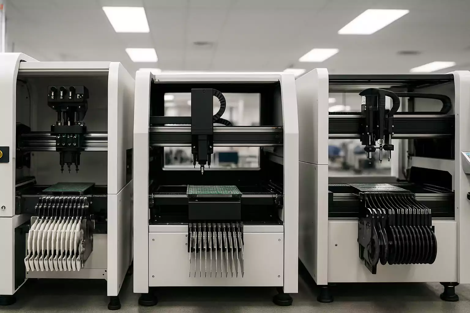
Pick-and-place machines have transformed SMT (Surface Mount Technology) assembly by automating the placement of components with incredible speed and accuracy. These machines are essential for building everything from smartphones to aerospace systems.
In this article, we’ll demystify how pick-and-place machines work, explore their key types and technologies, and share design tips to optimize your PCB layouts for automated assembly. Whether you're an engineer or managing outsourced production, understanding these machines can dramatically improve your product quality and time-to-market.
What Is a Pick-and-Place Machine?
A pick-and-place machine is a type of automated equipment used in Surface Mount Technology (SMT) to accurately place electronic components onto a printed circuit board (PCB). These machines are essential in modern electronics manufacturing, enabling the fast and precise assembly of everything from smartphones to industrial control systems.
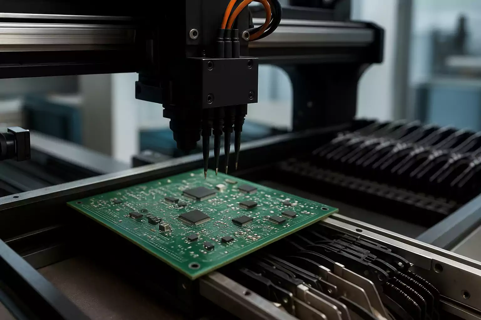
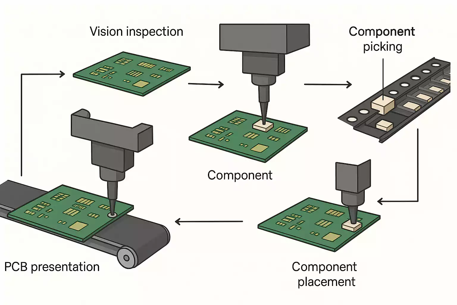
Unlike manual assembly, which is labor-intensive and prone to human error, pick-and-place machines use robotic arms, suction nozzles, and vision systems to handle components with micrometer-level precision. The process involves "picking" a component from a feeder or tray and "placing" it onto the designated pad on the PCB, which has already been prepped with solder paste.
Why Are Pick-and-Place Machines Important in PCB Assembly?
Pick-and-place systems are the workhorses of SMT production lines, offering unmatched speed, repeatability, and accuracy. Their impact is especially evident in high-volume production where placing thousands of components per hour with minimal error is critical.
Key functions of pick-and-place machines include:
- Component recognition via cameras and fiducials (alignment marks)
- High-speed placement of resistors, capacitors, ICs, and more
- Rotation and alignment of parts before placement
- Placement verification through vision inspection systems
Pick-and-place machines form the backbone of modern electronics assembly, allowing manufacturers to scale production efficiently while maintaining quality.
Types of Pick-and-Place Machines and Their Core Components
Pick-and-place (PnP) machines come in various configurations, each designed to suit different production needs—from high-speed consumer electronics to precision medical devices. Understanding the distinctions between the main types of machines and their internal components can help you choose the right equipment for your PCB assembly line.
Common Types of Pick-and-Place Machines
| Type | Key Feature | Best For | Speed | Placement Accuracy |
|---|---|---|---|---|
| Chip Shooter | Extremely fast placement with limited flexibility | High-volume production of simple PCBs | Very High (≥50k CPH) | Moderate (±50–100 μm) |
| Precision Placer | Slower, highly accurate head with advanced vision | Complex boards with fine-pitch parts | Moderate (10–20k CPH) | High (±20–40 μm) |
| Modular/Hybrid | Combines speed and accuracy with reconfigurable modules | Flexible production lines (prototypes to medium runs) | Scalable (based on config) | Adjustable |
Each type serves a specific niche. Chip shooters excel in raw throughput but may lack fine placement control, while precision placers are optimized for intricate components like BGAs or 0201 packages. Modular systems balance both, making them ideal for dynamic production environments.
Core Components of a Pick-and-Place Machine
Regardless of the machine type, all pick-and-place systems share several critical subsystems that determine their performance and reliability:
- Pick-and-Place Head (Nozzles): Uses vacuum or mechanical force to pick components from feeders and place them on PCBs.
- Vision System: Cameras detect fiducials on the board and verify component orientation for accurate placement.
- Feeders: Hold and advance components (tape, tray, or stick format) into pickup position.
- X-Y Gantry or Conveyor System: Controls machine movement to align the head and PCB.
- Control Software: Optimizes placement sequence, tracks feeder usage, and logs performance metrics.
- PCB Support Platform: Keeps the board stable during component placement to avoid vibrations or misalignment.
Key Functions and Technical Highlights of Pick-and-Place Machines
Pick-and-place machines are at the heart of SMT (Surface Mount Technology) assembly, and their efficiency hinges on several core functions and advanced technologies. Understanding these capabilities is crucial for engineers, buyers, and production managers seeking to optimize PCB assembly lines. Below, we break down the essential features that drive modern pick-and-place performance.
1. Vision Systems and Fiducial Recognition
One of the most critical technologies in a pick-and-place machine is its vision alignment system. Before placing any components, the machine uses high-resolution cameras to locate fiducial marks—reference points printed on the PCB surface. These marks help the system compensate for board skew or warping, ensuring micron-level placement accuracy.
Additionally, the vision system scans each component’s orientation, height, and polarity before placement. This reduces placement errors, especially for ICs, polarized capacitors, and LEDs, which must be mounted in a specific direction.
2. Multi-Nozzle and Parallel Placement Optimization
To boost throughput, high-end pick-and-place machines feature multiple placement heads (nozzles) working in parallel. Each head picks up different components from feeders and deposits them simultaneously on the PCB.
The placement software uses advanced algorithms to optimize:
- Head travel paths
- Feeder assignments
- Component pickup sequences
This path optimization reduces idle time and mechanical movement, directly translating into higher placement speed (CPH – components per hour) and improved operational efficiency.
3. Real-Time Software Control and Error Monitoring
Modern machines are powered by robust software platforms that allow real-time control and diagnostics. Operators can:
- Monitor machine status
- Analyze placement quality
- Adjust feeder locations and speeds
- Log placement errors for traceability
Advanced systems even include self-calibration routines and predictive maintenance alerts, using sensor data to anticipate wear or misalignment before they cause production delays.
4. Intelligent Feeder Systems
Component feeders have evolved significantly. Smart feeders now offer features like:
- Automatic pitch detection
- Barcode/QR code scanning for component traceability
- Error alerts when components are loaded incorrectly
These systems ensure the right component is always picked and placed, minimizing feeder errors, one of the most common causes of line stoppage.
5. Placement Accuracy and Speed Balancing
While speed is a key selling point, placement accuracy remains critical—especially for high-density boards, fine-pitch components, or BGA packages. High-performance machines balance both by:
- Using linear motor drives for smooth, vibration-free motion
- Incorporating advanced gantry systems with minimal backlash
- Employing laser and optical centering systems
Trends and Technical Challenges in Pick-and-Place Machines
AI-Powered Optimization
Modern pick-and-place machines are increasingly integrating artificial intelligence to optimize component placement. AI algorithms analyze placement patterns, detect inefficiencies, and continuously improve head movement paths to reduce cycle time. This trend not only boosts throughput but also supports smarter error detection and adaptive learning systems.
Integration with Smart Factory Systems (Industry 4.0)
The rise of Industry 4.0 has led to a growing demand for machines that communicate with other equipment on the production floor. Pick-and-place systems are now being designed with IoT connectivity, enabling real-time monitoring, remote diagnostics, and seamless MES/ERP integration. This ensures traceability, predictive maintenance, and efficient inventory control.
Miniaturization and High-Density Components
As consumer electronics continue to shrink in size, pick-and-place machines face the challenge of accurately placing ultra-small components such as 01005 and 0201 packages. These components require advanced vision systems, ultra-precise nozzles, and vibration-free handling to ensure reliable placement at high speeds.
Energy Efficiency and Sustainability
Manufacturers are also pushing for greener operations. New-generation machines are being developed with energy-efficient motors, intelligent standby modes, and optimized compressed air usage. These upgrades contribute to reduced energy consumption and align with global sustainability goals.
Flexibility for Low-Volume, High-Mix Production
With the rise in custom electronics and prototyping, pick-and-place machines must now support quick changeovers and adaptable feeder setups. Machines with modular heads and smart software are better suited for high-mix, low-volume assembly environments without compromising on placement accuracy or speed.
Design and Application Optimization Tips for Pick-and-Place Machines
Optimize Component Placement in PCB Design
Efficient component layout is critical to reducing pick-and-place cycle time. Group similar components together, align parts with consistent orientation, and minimize rotational variance. This reduces head travel and improves overall throughput, especially in high-volume runs.
Choose Pick-and-Place Friendly Footprints
Use standardized and machine-friendly component footprints in your PCB design. Avoid overly tight pitches or irregular pad shapes that can confuse vision systems or complicate nozzle pickup. Check IPC standards and your assembler’s machine capabilities before finalizing the design.
Use Fiducials and Keep-Out Zones Wisely
Ensure global and local fiducials are placed clearly and away from copper pours or silkscreen. Fiducials help the pick-and-place machine align the board accurately. Also, define keep-out zones around connectors or mechanical parts to prevent nozzle collisions during placement.
Plan for Feeder and Reel Compatibility
Design your BOM and board layout with available feeder types in mind. Avoid excessive component variety that may exceed feeder capacity or complicate reel changes. Where possible, consolidate passive components using common values to streamline the assembly process.
Maintain Proper Orientation and Polarity Markings
Incorrect or missing polarity and orientation indicators can lead to manual inspection delays or placement errors. Always include clear polarity markings on silkscreen layers, and align polarized parts (diodes, LEDs, ICs) in the same direction across the board where feasible.
Prepare for High-Density or Fine-Pitch Assembly
If your design includes fine-pitch components (e.g., QFNs, BGAs), ensure pad and solder mask openings follow recommended specs. Also, consult with your assembler about stencil and placement tolerances to prevent bridging or misalignment during reflow.
Typical Applications and Use Case Comparisons
Pick-and-place machines are not one-size-fits-all. Their performance and suitability can vary greatly depending on the production scale, board complexity, and component types. Understanding how these machines function across different applications is crucial for selecting the right equipment and optimizing your SMT process.
Prototyping vs. High-Volume Production
In prototyping and small-batch assembly, flexibility and fast changeover are top priorities. Machines used in this context often feature:
- Easy programming interfaces for quick job setup
- Manual or semi-automated feeders
- Lower placement speed but higher adaptability
- Compatibility with open-source or benchtop systems (e.g., LumenPnP)
These systems are ideal for R&D environments, startups, and rapid iterations where design changes happen frequently.
In contrast, high-volume production lines demand:
- Ultra-high-speed placement heads (up to 100,000 CPH or more)
- Advanced vision alignment and fiducial recognition
- Multi-lane feeders and auto splicing for continuous operation
- Real-time monitoring and traceability features
Such machines are commonly used in large EMS (Electronics Manufacturing Services) providers and OEM production lines for consumer electronics, automotive, and medical devices.
High-Density vs. General-Purpose PCB Assembly
Boards with high component density, such as those used in smartphones, wearables, or compact IoT devices, require machines capable of:
- Placing micro-components like 0201 or even 01005 packages
- Precision alignment for BGA, QFN, and fine-pitch ICs
- Maintaining tight tolerance in thermal and mechanical stress
Here, high-resolution cameras and multi-angle vision systems are essential to avoid misplacement and ensure soldering quality.
Meanwhile, general-purpose PCBs (like industrial controllers or LED drivers) may not require the same level of precision. Mid-range pick-and-place machines that balance speed, cost, and usability often suffice. These machines can still offer strong ROI without the overhead of ultra-fine placement capabilities.
Hybrid Production Scenarios
In many modern factories, a hybrid approach is used—combining high-speed machines for standard parts (e.g., resistors, capacitors) with precision machines for complex components. This allows for optimal throughput without sacrificing placement accuracy where it matters most.
Common Mistakes and Pitfalls to Avoid
Even with advanced pick-and-place machines, errors and inefficiencies often stem from human decisions. Here are key mistakes to avoid:
1. Overvaluing Speed Ratings
High “placements per hour” (PPH) specs can be misleading. These are often measured under ideal lab conditions, not real-world production.
Avoid this by: Prioritize real throughput and placement accuracy over peak speed claims.
2. Mismatched Machine Type
Using high-speed machines for complex components, or precision placers for high-volume jobs, leads to inefficiencies.
Avoid this by: Choose equipment based on your component variety and production volume.
3. Poor Vision System Usage
Misaligned fiducials, dirty lenses, or skipped calibration can cause serious placement errors.
Avoid this by: Maintain cameras, use proper fiducial design, and calibrate regularly.
4. Ignoring Preventive Maintenance
Skipping maintenance leads to nozzle clogging, feeder errors, and downtime.
Avoid this by: Follow a strict maintenance schedule and log calibration checks.
5. Inefficient Feeder Layout
Scattered or incompatible feeders slow down cycles and cause part loss.
Avoid this by: Group high-use components and check feeder compatibility before each run.
FAQ: Pick-and-Place Machines in PCB Assembly
What is a pick-and-place machine, and why is it important in PCB assembly?
A pick-and-place machine is an automated system that places surface-mount components onto PCBs with high speed and accuracy. It’s essential for efficient, reliable SMT assembly—especially in high-volume or high-density production.
How does a pick-and-place machine know where to place each component?
The machine uses PCB design files (like Gerber and BOM) and optical alignment with fiducial markers to determine precise component placement on the board.
Can pick-and-place machines handle very small or unusual components?
Yes. Modern machines can place ultra-small parts like 0201 packages and support odd-shaped components, though special nozzles or slower placement may be needed.
How do I choose the right pick-and-place machine for my needs?
Key factors include:
•Production volume (prototype vs. mass production)
•Required placement accuracy
•Supported component sizes
•Integration with existing SMT equipment
•Budget and available space
Conclusion: Bridging Precision and Efficiency in Modern PCB Assembly
Pick-and-place machines are at the heart of today’s high-speed, high-precision PCB assembly lines. From placing thousands of components per hour with pinpoint accuracy to enabling rapid prototyping and scalable production, these machines are critical for delivering quality and efficiency in electronics manufacturing.
As PCB designs become more compact and component densities increase, selecting the right pick-and-place solution—and understanding its capabilities—becomes essential. Whether you're working with high-volume production or low-run prototypes, mastering the technology behind these machines can significantly improve yield, reduce downtime, and future-proof your assembly process.