

Printed circuit boards (PCBs) come in many forms depending on their structure, material, and application.
From the simplest single-sided boards to high-end backplanes and rigid-flex circuits, PCB types vary in cost, reliability, wiring density, and manufacturing complexity.
This guide explains the most common types of PCB, their construction, and their typical use cases.
Single-Sided and Double-Sided PCB
1. Single-Sided PCB
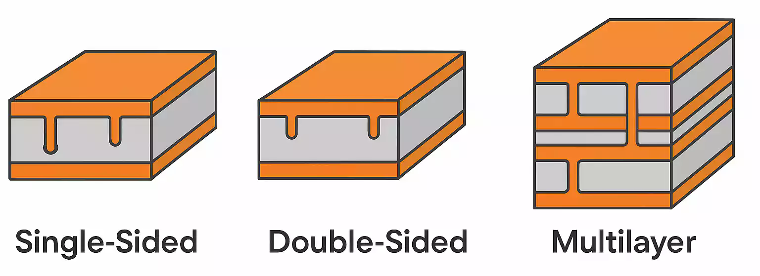
A single-sided PCB has conductive copper traces on only one side of the board, with the other side typically made of an insulating substrate.
It is the most straightforward and most economical PCB type.
Key Features:
- Low wiring density
- Simple manufacturing process
- Very low cost
- Limited functionality — not suitable for complex circuits
Since all traces are on a single surface, routing options are limited. Single-sided PCBs are best suited for simple, low-component circuits.
Typical Applications:
- Basic consumer electronics
- Low-cost appliances
- Simple control circuits
2. Double-Sided PCB
A double-sided PCB has copper layers on both sides of the substrate, allowing traces and components to be placed on both surfaces.
Conductive paths between the two sides are made using plated through-holes (PTH) or vias.
Key Features:
- Higher routing density than single-sided boards
- Components can be mounted on both sides.
- Moderate cost
- Ideal for medium-complexity circuits
Common Materials:
- Paper-based resin board for consumer electronics
- Low-loss PTFE (Teflon) for RF and microwave circuits
Typical Applications:
- Consumer electronics
- Automotive electronics
- RF and microwave systems
Single-sided and double-sided boards are the most cost-effective PCB types for mass-market products.
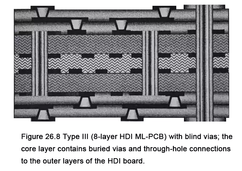
Multilayer PCB
A multilayer PCB contains more than two conductive layers — typically three or more — laminated together under heat and pressure.
Structural Features:
- Inner layers interconnected by plated vias
- Outer layers used for signal or power distribution
- Continuous power and ground planes for noise reduction
Multilayer PCBs improve signal integrity, power distribution, and EMI performance — making them essential for high-speed and high-density electronic systems.
Typical Layer Counts:
- 3 to 50 layers, depending on system complexity
Material Composition:
- Fiberglass cloth reinforced with epoxy or other resin systems.
- Offers high thermal stability, controlled dielectric constant, and chemical resistance
Typical Applications:
- Personal computers and servers
- Networking and communication equipment
- High-speed digital systems
- Supercomputers
Most complex digital systems rely on multilayer PCB types for performance and compactness.
Discrete Wiring or Multiwire PCB
The discrete wiring PCB (or multiwire PCB) evolved from multilayer technology, replacing traditional etched signal layers with individually formed wiring patterns.
Manufacturing Process Overview:
- Power planes are etched on both sides of the substrate.
- Semi-cured adhesive prepregs are laminated on each side.
- Discrete wires or conductors are embedded or rolled into the adhesive layers following the layout design.
- A second laminate is added, and the board is pressed, drilled, and finished like a standard multilayer PCB.
Core Characteristics:
- Electrically similar to multilayer PCBs
- Discrete wire layers replace signal layers.
- Ideal for high-density routing where isolation is critical
Designing discrete wiring PCBs requires dedicated CAD tools to generate accurate wire-path data. The method enables flexible routing and rapid design changes but is less practical for mass production because of its higher complexity and cost.
In prototyping, discrete wiring PCBs offer fast turnaround and low tooling requirements. For mass production, however, standard multilayer PCBs remain more cost-effective and easier to manufacture consistently.
Hybrid Circuit Boards
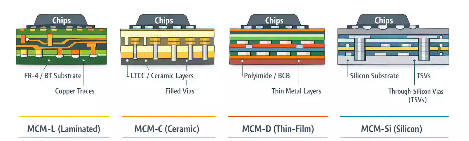
Hybrid circuit boards combine ceramic substrates with printed resistors and surface-mounted components, bridging PCB and thick-film technologies.
Typical Structure:
- Single or double-sided ceramic base
- Surface-mounted active components
- Metal pastes are used to print resistor networks.
Advantages:
- Compact size
- Excellent thermal and dimensional stability
- High reliability for miniature designs
Typical Applications:
- Hearing aids
- Miniature medical devices
- Specialized compact electronics
Flexible PCB (FPC)
Flexible PCBs are made by laminating copper foil onto a flexible substrate such as polyimide (PI) or aramid fiber films.
They can bend, fold, or twist while maintaining electrical continuity.
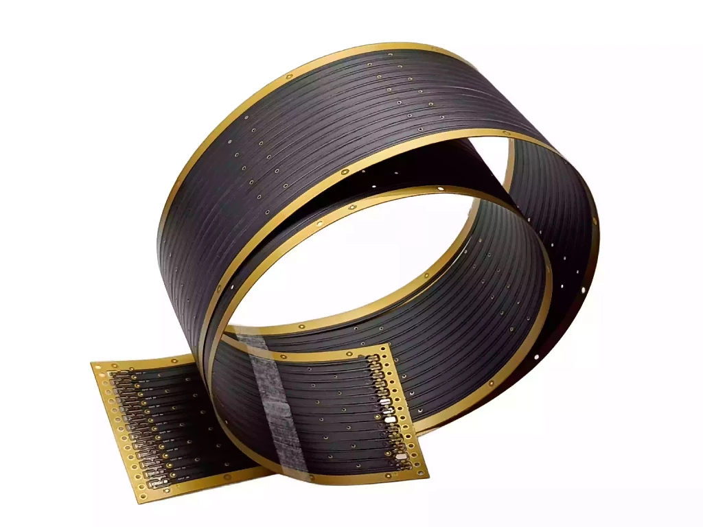
Key Structural Features:
- Available in single-, double-, or multilayer configurations
- Can replace traditional wiring harnesses
- Lightweight and space-saving
Advantages:
- Reduces connectors and interconnect failures
- Saves assembly space
- Improves mechanical flexibility and reliability
Typical Applications:
- Cameras
- Printers and disk drives
- Aerospace electronics
- Video recorders
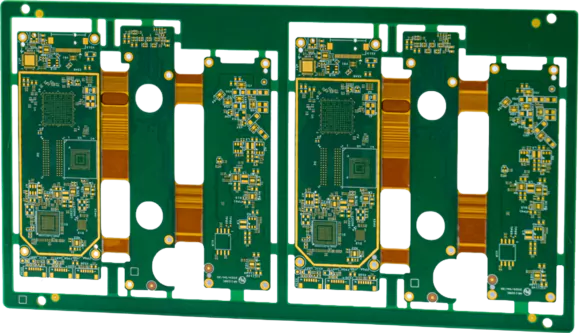
Rigid-Flex PCB
A rigid-flex PCB combines rigid and flexible layers into a single unified structure.
The flexible section is manufactured first, then laminated to the rigid portion.
Process Characteristics:
- Continuous electrical connections across rigid and flex regions
- Eliminates the need for connectors and cables
Core Advantages:
- Enhanced reliability and compactness
- Simplified assembly
- Improved mechanical integrity
Typical Applications:
- Aerospace and avionics systems
- Portable electronics (e.g., laptops, foldable devices)
Cost Considerations:
- More expensive than separate rigid PCBs and cables
- Offers superior performance for high-reliability designs
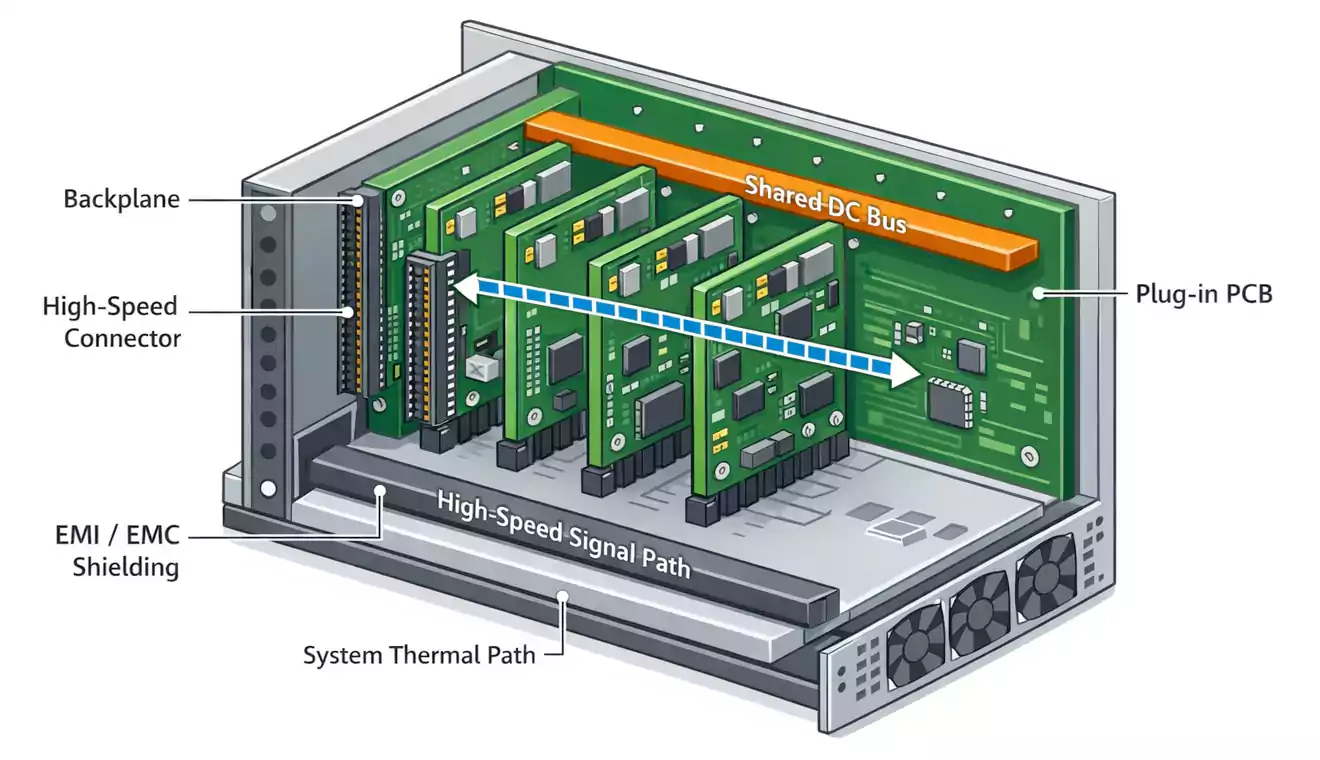
Backplane PCB
A backplane is a specialized multilayer PCB type used for high-density system interconnections and power distribution.
Structural Features:
- Contains numerous press-fit connectors
- Multiple embedded power layers
- Handles high DC distribution
Power Delivery:
- Internal power planes are laminated within the structure.
- External busbars or studs connect to power surfaces.
Some advanced backplane designs integrate surface-mounted active components, such as ICs, to enhance functionality and signal control.
However, their large size and thickness create significant manufacturing challenges. The high thermal mass makes soldering fine-pitch components difficult, requiring precise temperature control and specialized assembly processes to ensure reliability.
FAQ: PCB Types
What are the main PCB types?
Single-sided, double-sided, multilayer, rigid, flex, rigid-flex; backplanes are a specialized multilayer form.
Single-sided vs. double-sided — what’s the key difference?
Single-sided has copper on one face (lowest cost, limited routing). Double-sided has copper on both faces with plated through-holes/vias for interconnect (denser layouts, moderate cost).
When should I choose a multilayer PCB?
When you need higher routing density, controlled impedance, solid power/ground planes, and better SI/PI/EMI for high-speed or complex systems.
Rigid vs. flex vs. rigid-flex — how do I decide?
Rigid = lowest cost, best for fixed enclosures.
Flex = bends to save space and reduce connectors.
Rigid-flex = highest reliability where cables/connectors are weak points (higher board cost, lower system risk).
What is a backplane PCB?
A large, thick multilayer board with many press-fit connectors and heavy copper planes to interconnect plug-in cards and distribute high DC current at the system level.
Conclusion
From single-sided to rigid-flex and backplane designs, the wide range of PCB types offers engineers flexibility in balancing performance, cost, and manufacturability.
Understanding the different types of PCB is essential for selecting the right substrate, layer structure, and interconnect strategy in any modern electronic design.
