In high-speed and RF PCB design, the PCB substrate plays a decisive role in signal integrity and overall system reliability. The choice of PCB substrate materials directly affects impedance control, transmission loss, and thermal stability.
This article explains how to select the right PCB substrate based on dielectric constant (Dk) and dissipation factor (Df), how resin and reinforcement types influence electrical behavior, and how to balance performance, manufacturability, and cost.
Understanding Dielectric Behavior in PCB Substrates
Two core electrical parameters define a PCB substrate’s performance:
- Dielectric Constant (Dk) — determines signal propagation speed through the substrate.
- Dissipation Factor (Df) — measures signal loss as heat within the PCB substrate material.
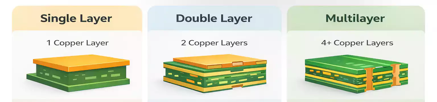
Both are strongly influenced by the resin system and reinforcing material used in the substrate. These determine how efficiently and consistently a signal travels through the multilayer PCB stack-up.
Common Types of Low-Dk and Low-Loss PCB Substrate Materials
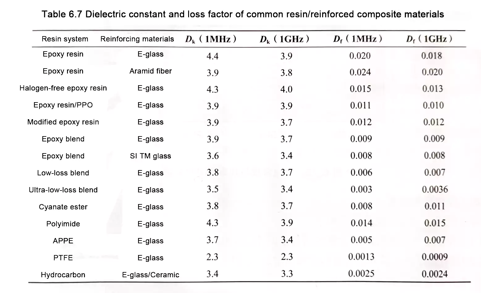
For high-speed circuits and RF applications, engineers must choose low-Dk, low-loss PCB substrates. The most widely used resin systems include:
- PTFE (Teflon) — an ultra-low-loss PCB substrate ideal for microwave and mmWave frequencies.
- Cyanate Ester — stable high-frequency PCB substrate with low moisture absorption.
- Epoxy Blends — cost-effective PCB substrates for mid- to high-speed applications.
- Allylated Polyphenylene Ether (APPE) — provides stable Dk/Df and good thermal reliability.
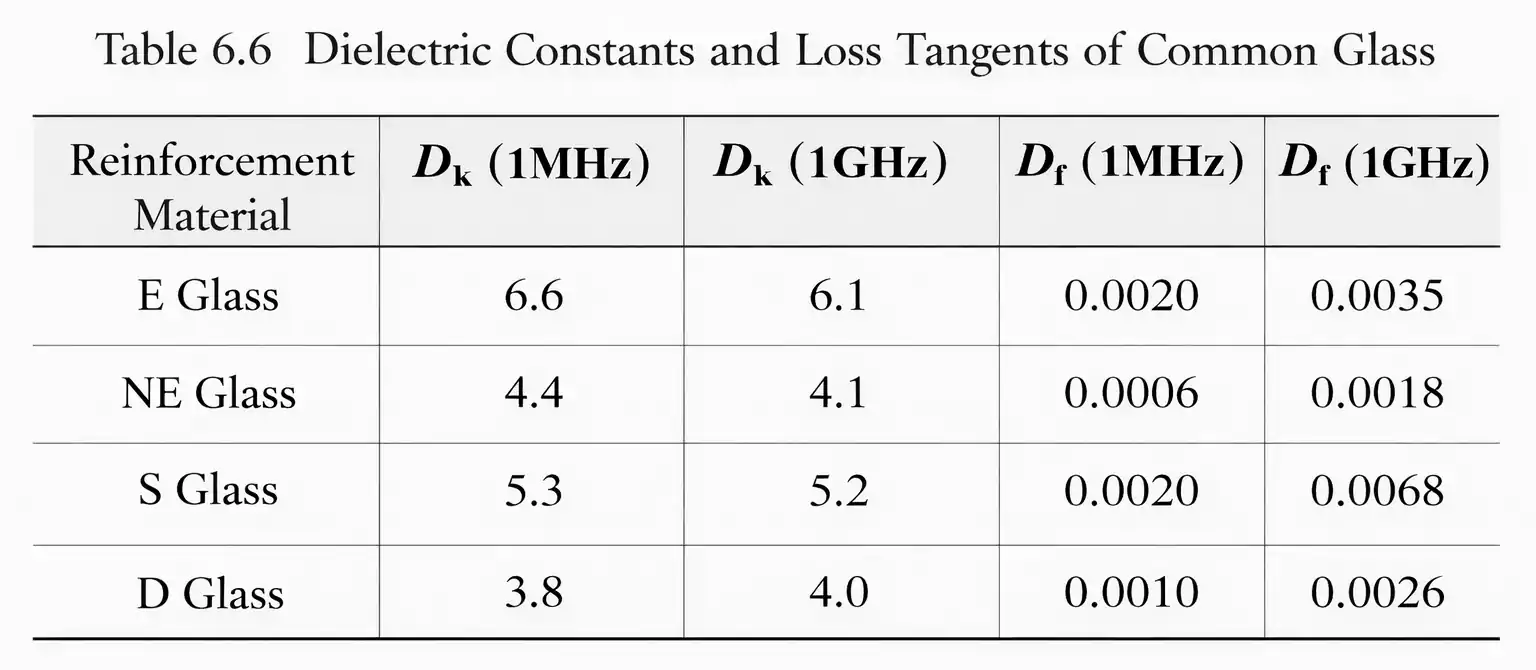
In addition, reinforcement materials such as E-glass or modified glass fabrics, and inorganic fillers such as ceramic powder, can fine-tune the electrical performance of the PCB substrate.
Resin Content and Reinforcement Effects
Typical data tables (like Tables 6.6 and 6.7) assume about 50% resin content, but actual electrical properties vary with the resin ratio and specific resin chemistry.
- Even within the same “epoxy” family, dielectric properties can differ by supplier.
- Special formulations can offer slightly different Dk and Df values.
- Test methods—especially at high frequencies—significantly affect measured results.
When comparing materials, it’s critical to use the same test method and frequency conditions to avoid misleading conclusions.
Frequency, Resin Ratio, and Environmental Influences
The relationship between Dk, Df, and other variables can be summarized as follows:
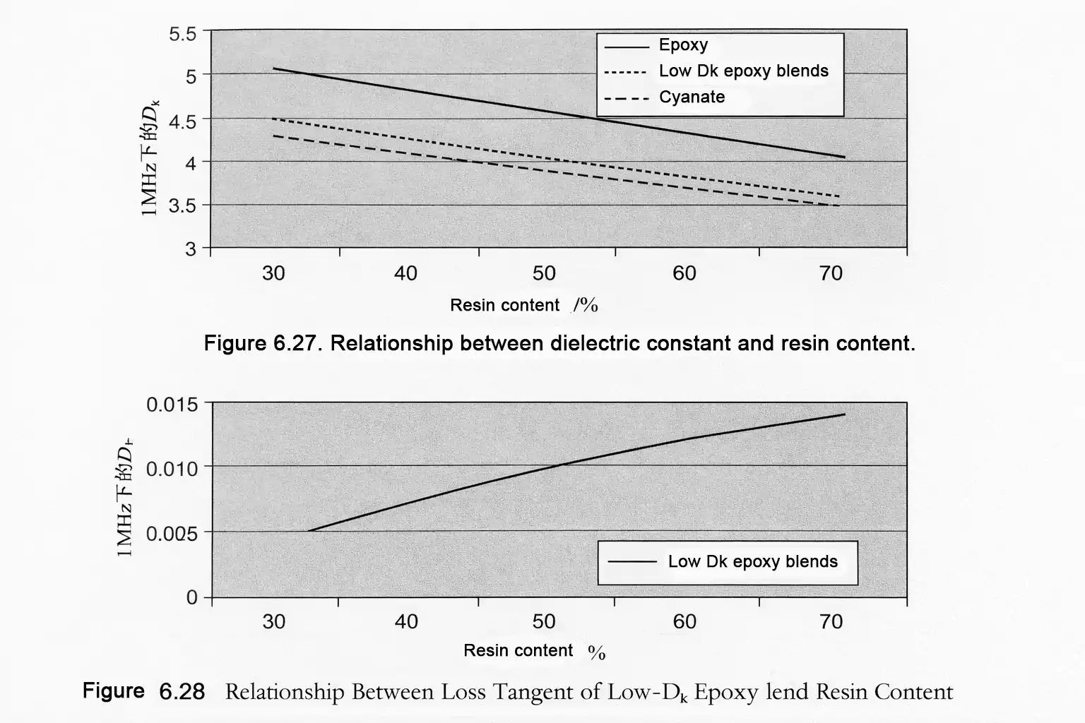
- Dk decreases as resin content increases (since most resins have lower Dk than glass).
- Df increases as resin content increases (resins typically have higher loss than glass).
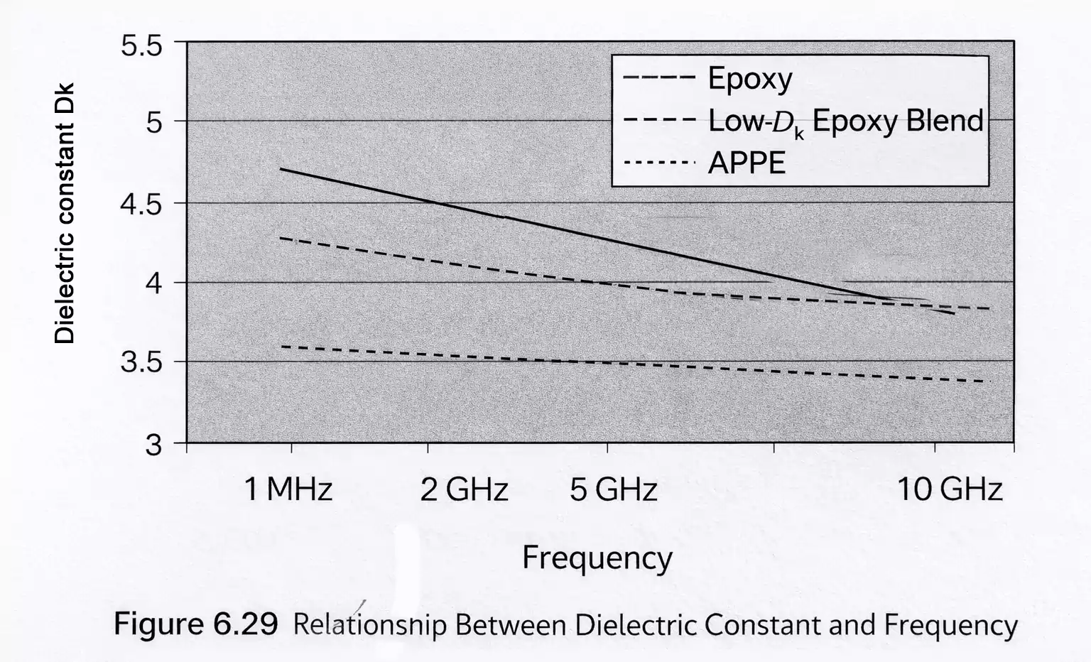
- Dk slightly decreases with increasing frequency.
- Df generally increases with frequency, sometimes reaching a peak at certain bands.
- Temperature and moisture absorption both increase Dk and Df.
- E-glass shows little frequency dependence, making low-resin laminates more stable across frequency ranges.
These effects are critical for high-speed digital, RF, and wireless systems, where impedance control and signal integrity depend on stable dielectric behavior across frequency and environmental variations.
Matching PCB Substrate to Application and Environment
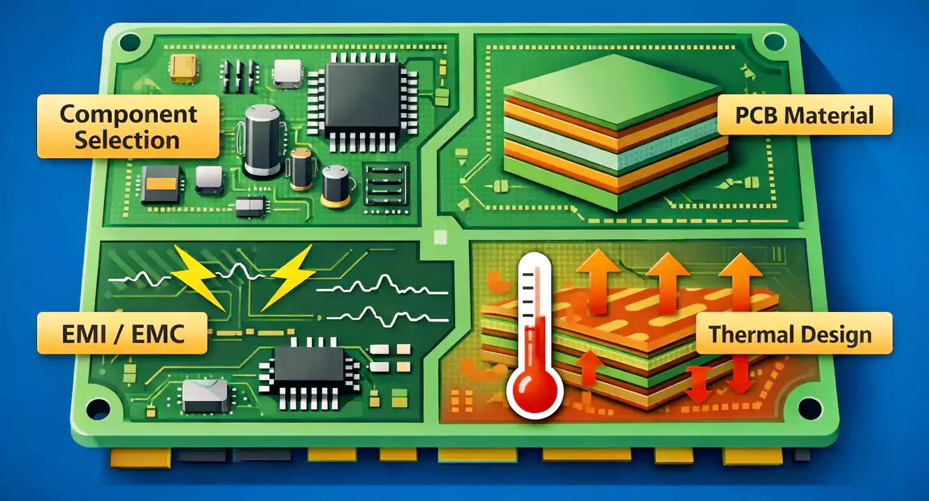
Choosing a substrate is not just about electrical numbers—it’s about operational context.
Different resin systems respond differently to changes in temperature, humidity, and frequency:
- Advanced materials like cyanate ester or PTFE maintain stable performance across a wide range of frequencies and environments.
- Standard FR-4 or mid-tier epoxy systems may exhibit noticeable shifts under high humidity or temperature.
Material suppliers continually refine resin systems to meet the demands of high-speed digital and wireless applications, ensuring consistent performance under variable conditions.
Balancing PCB Substrate Performance, Cost, and Manufacturability
A common misconception is that the “best” PCB material is simply the one with the lowest Dk and Df.
In practice, engineering is about balance:
- Lower-Dk/Df materials are more expensive.
- They’re also harder to fabricate (PTFE, for instance, requires specialized lamination and drilling processes).
- Production yield and stability may suffer if the material is not well-controlled.
Therefore, the optimal choice is often the lowest-cost material that still meets design requirements for signal integrity, loss budget, and manufacturability.
Key Dielectric Relationships for PCB Substrates
To summarize the main relationships:
- Df increases with frequency, but may peak at specific frequencies depending on material chemistry.
- Dk decreases as resin content increases.
- Df increases as resin content increases.
- Dk slightly decreases with rising frequency.
- Both Dk and Df increase with moisture absorption.
- E-glass Dk is nearly frequency-independent.
Conclusion: Engineering the Right PCB Substrate for Signal Integrity
Selecting the right PCB material isn’t just about data sheets—it’s about understanding how resin systems, reinforcement types, resin content, frequency, and environmental factors interact in the real world.
In the era of 5G, high-speed computing, and advanced wireless systems, material engineering has become as important as circuit design itself. The right substrate is the foundation for signal integrity, reliability, and long-term performance.