


When building or repairing electronic products, connecting external wires to a PCB is always a key step. One of the most practical ways to do this is with a PCB screw terminal, also called a terminal block or connector block.
These small green or blue blocks let you insert wires, tighten them with screws, and make a solid electrical and mechanical connection. They are found in everything from LED drivers and power supplies to automation panels and IoT boards.
This guide first defines PCB screw terminals, then details types, selection criteria for size and pitch, and compares them to soldered options.
What Is a PCB Screw Terminal?
A PCB screw terminal is a connector mounted on a printed circuit board that lets you attach external wires with screws or clamps rather than soldering.
Each terminal usually has a metal cage, a screw, and one or more pins soldered to the PCB. When you tighten the screw, it presses the wire against the metal contact, forming a secure connection.
This design is perfect when you need to connect or disconnect wires easily—such as during testing, field installation, or maintenance. That’s why they are common in industrial equipment, control boards, lighting systems, and lab instruments.
Screw Terminal vs. Terminal Block vs. Connector
People often use these names interchangeably, which can be confusing.
- Screw terminal: focuses on the screw-type fastening method.
- Terminal block: a broader family of multi-position connectors, which may use screws, springs, or push-in clamps.
- PCB connector: a wider category that also includes wire-to-board, board-to-board, and edge connectors.
In short, a PCB screw terminal block is a type of wire-to-board connector that uses screws to hold wires firmly in place. When you see 2-pin, 3-pin, or 4-pin “terminal blocks” on a board, those are screw terminals.
Common Types of PCB Screw Terminals
Key structural differences determine terminal operation. Understanding these helps select the appropriate model.
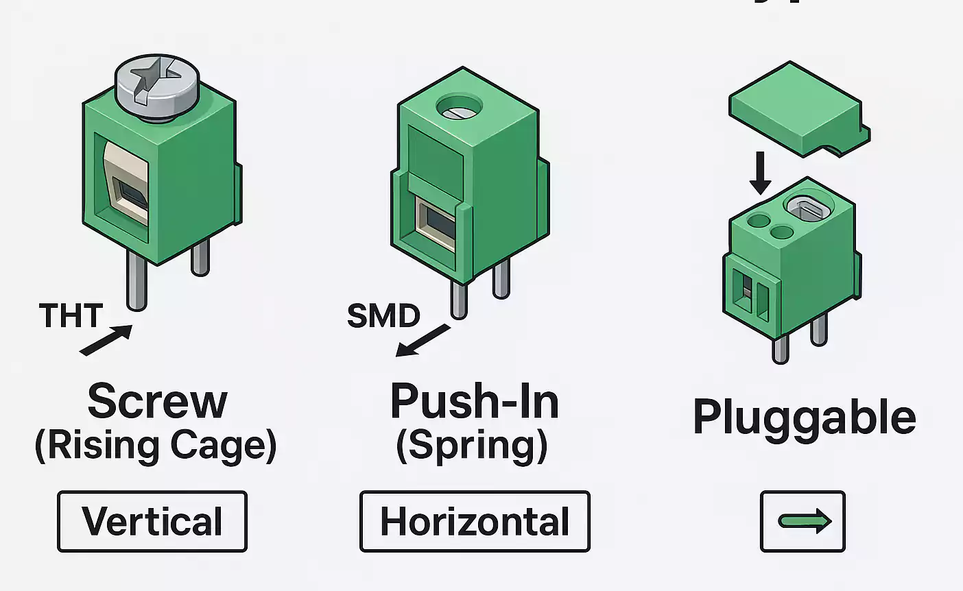
- Screw or Rising Cage Type
The traditional design uses a screw and a metal clamp (cage). Tightening the screw lifts the cage and traps the wire. It’s strong, simple, and affordable—good for power and control lines. - Push-in or Spring Clamp Type
Instead of a screw, a spring clip or lever holds the wire. You just push the stripped wire in, and the spring keeps tension. This saves time and avoids over-tightening. Great for high-vibration or frequent re-wiring situations. - Plug-in or Pluggable Terminal Block
Comes in two parts: a plug and a base. The plug connects to the wire; the base is soldered to the PCB. You can unplug it without desoldering—ideal for maintenance. - Mounting Styles
- THT (Through-Hole): pins go through holes in the PCB and are soldered from the bottom. This type is mechanically stronger and used for larger currents.
- SMD (Surface-Mount): sits on the PCB surface; good for automated assembly but less rugged.
- Wire Exit Direction
- Vertical (90°): wire exits straight up.
- Horizontal (180°): wire exits parallel to the board surface.
Typical Specifications: Pitch, Pins, and Wire Size
Terminal block specs like '5.08 mm pitch, 2-pin, 10 A' identify size, connections, and capacity. Here’s what those mean.
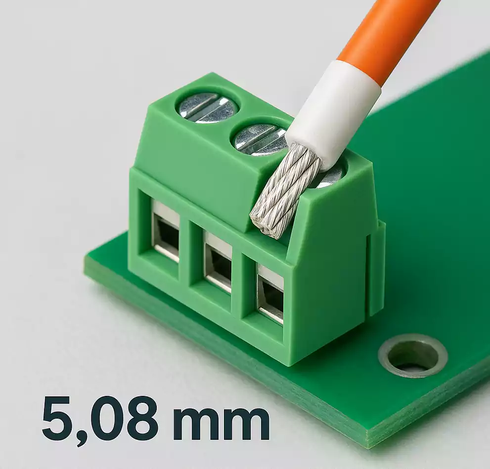
- Pitch (Pin Spacing) – the distance between two pins.
Common pitches are 2.54 mm, 3.5 mm, 5.0/5.08 mm, and 7.62 mm.
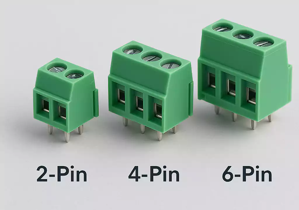
Smaller pitch = higher density, lower voltage/current. A larger pitch provides more clearance and higher power capability. - Number of Pins (Positions) – how many connections per block (2, 3, 4, 6, 12, etc.).
You can combine blocks end-to-end to create custom lengths. - Current and Voltage Rating – depends on pitch, contact metal, and wire gauge.
For example, a 3.5 mm block might handle 8 A, while a 7.62 mm one can handle 15–20 A. - Wire Gauge (AWG) – the size of the wire the terminal can accept.
Most handle 26–12 AWG. For fine-stranded wires, adding a ferrule improves reliability. - Materials –
- Contacts: brass or copper alloy, usually tin- or nickel-plated.
- Housing: flame-retardant PA66 (UL94 V-0).
- Screws: steel or brass, often with zinc or nickel plating.
Quick Pitch–Current–Application Table
| 2.54 mm | <2 A | Prototype boards, sensors |
| 3.5 mm | 5–8 A | Control signals, I/O modules |
| 5.08 mm | 10–15 A | Power supply, lighting, relays |
| 7.62 mm | 15–20 A | Industrial power, motor drivers |
How to Choose the Right PCB Screw Terminal
- Define the Circuit Type and Current
Is it for signal, control, or power? Choose a terminal rated 20–30 % above your maximum current for a safety margin. - Match the Wire Type and Convenience
Solid or stranded? If you rewire often or want tool-free operation, go for push-in or spring types. - Check the Mounting and Space
THT for strength, SMD for automation.
Vertical exit saves board area; horizontal fits better in low-profile enclosures. - Select Pitch and Number of Pins
3.5 mm for compact control boards, 5.08 mm for power.
Two or three pins handle DC in/out; four or six pins fit multi-channel modules. - Confirm Standards and Brand Options
Reliable suppliers like Phoenix Contact, WAGO, TE Connectivity, and OMRON offer UL/IEC-certified parts and wide compatibility with distributors such as Digi-Key and Mouser.
Screw Terminals vs. Soldered Connections
Both methods have their place. Here’s a quick comparison.
| Ease of Installation | Simple, no soldering skill needed | Requires soldering tools |
| Re-usability | Can connect/disconnect many times | Permanent |
| Mechanical Strength | High (especially THT) | Depends on solder joint |
| Vibration Resistance | Good (spring types best) | Average |
| Cost & Size | Slightly higher, larger footprint | Lower cost, compact |
| Best For | Field wiring, maintenance, modular systems | Mass-produced fixed designs |
If your product requires field wiring or serviceability, choose a screw- or push-in-terminal.
For compact, permanent, and low-cost connections, soldering is preferable.
Safety and Reliability Tips
Screw terminals are safe when installed correctly. Keep these simple points in mind:
- Always stay within the rated current and voltage.
- Use the correct wire size; don’t force an oversized conductor.
- Strip only enough insulation to prevent bare wire from protruding beyond the terminal.
- Tighten screws firmly (finger-tight, not excessive).
- For stranded wires, crimp ferrules for consistent clamping.
- Select parts with UL, cULus, or IEC certifications for your region.
Modern push-in and spring-clamp designs are even more reliable in vibration environments since they maintain pressure automatically. Many industrial systems now prefer them for long-term stability.
Popular Sizes and Applications
Different pitches fit different current ranges and space limits. Here are the most used ones in PCB design:
- 2.54 mm (0.1") – very compact, ideal for prototypes and low-current signal boards.
- 3.5 mm / 3.81 mm – popular for sensor and I/O connections in automation and smart devices.
- 5.0 / 5.08 mm – the most common “general-purpose” pitch used for power supplies, LED drivers, and controller boards.
- 7.5 / 7.62 mm – used when voltage or current is higher, such as motor controllers and industrial power modules.
Typical Applications:
- Industrial control and PLC boards
- Building automation and security systems
- LED lighting drivers
- Motor and pump control modules
- Communication equipment
- Power supplies and converters
- Development kits and educational electronics
FAQ: People Also Ask
What is a screw terminal?
It’s a connector that uses a screw to clamp a wire into a metal contact on a PCB or device. It allows quick and secure wiring without soldering.
Are screw terminals better than soldering?
They’re better when you need easy wiring, replacement, or maintenance. Soldering is better for compact, permanent, low-cost connections. It depends on the project.
Are screw terminals safe to use?
Yes. When used within their rated limits and tightened properly, they are safe and reliable. Certified parts follow UL and IEC safety standards.
How reliable are screw terminals?
Very reliable for industrial and control applications. Modern rising-cage and spring-clamp types maintain strong pressure even under vibration and temperature changes.
Which pitch should I choose?
For small signals, 2.54–3.5 mm; for power, 5.08 mm or larger. If you’re unsure, 5.08 mm is the most versatile standard pitch for mixed-voltage boards.
Summary
PCB screw terminals offer a straightforward, reliable solution for connecting wires to PCBs, ensuring mechanical and electrical stability and simplifying maintenance.
Understanding parameters such as pitch, pin count, current, and wire size helps you select the most suitable PCB screw terminal for your application.
Using quality screw terminal blocks streamlines assembly and maintenance for a range of applications, from small sensor boards to industrial controllers.
