


If you open any electronic device—a smartphone, router, or LED driver—you’ll find a printed circuit board (PCB) at its heart. While the copper traces get all the visual attention, it’s the PCB material underneath that determines how the board performs under heat, high speed, and mechanical stress.
This guide explains what PCB materials are, the most common types, their key properties, and how to pick the right one for your design.
What Is PCB Material?
A PCB material (or substrate) is the base layer that supports copper traces and components. It provides the mechanical strength to hold parts in place and the insulation needed to keep electrical signals from shorting.
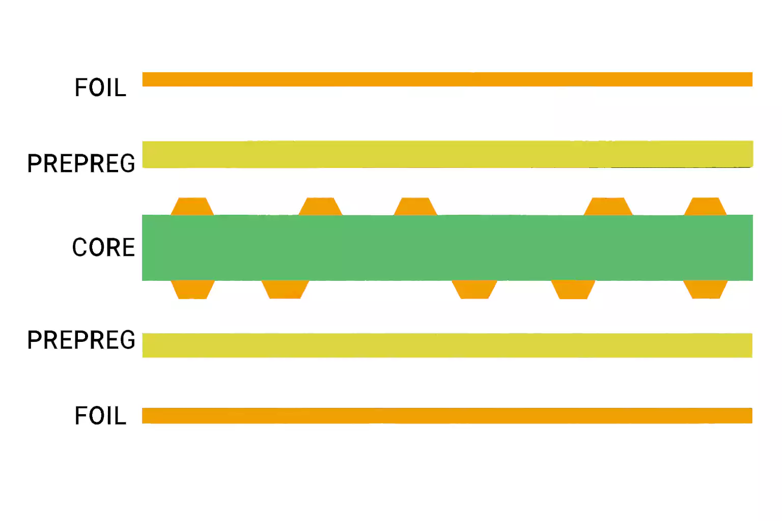
A typical multilayer PCB is made of:
- Copper foil for circuits
- Dielectric substrate (the “PCB material”)
- Solder mask and silkscreen for protection and labelling
The substrate’s electrical and thermal behaviour—its dielectric constant (Dk), dissipation factor (Df), glass transition temperature (Tg), and thermal expansion (CTE)—affects everything from impedance control to solder reliability.
Quick Selection by Application
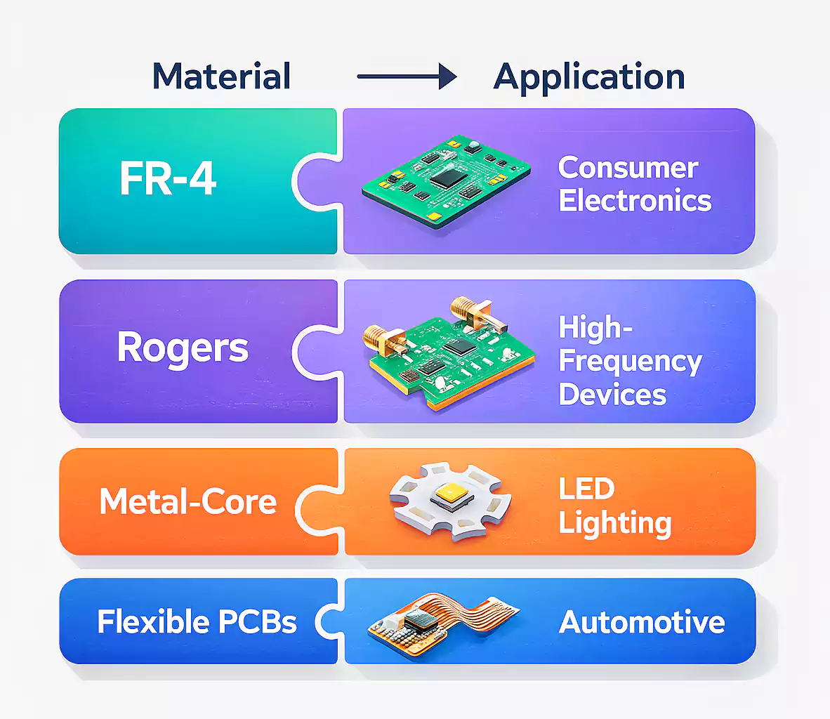
Choosing a PCB material starts with where the board will be used. Here’s a fast matching guide:
| High-speed / RF / 5G | Rogers, PTFE, or LCP | Very low Dk and Df for signal integrity |
| High temperature or flexible | Polyimide, flex PCB | Stable under repeated heat cycles and bending |
| Power / LED / heat dissipation | Metal-core or ceramic | Excellent thermal conductivity |
| General electronics | FR-4 (standard or high-Tg) | Best balance of cost, performance, and manufacturability |
PCB Materials List and Comparison
Below is a simplified PCB materials list that covers the most common types and their properties.
| FR-4 (standard) | 4.2–4.8 | 0.015–0.020 | 130–140 | 55–70 | 0.3 | 1.85 | ★ | Consumer electronics, industrial control |
| High-Tg FR-4 | 4.2–4.5 | 0.014–0.018 | 170–180 | 50–60 | 0.3 | 1.85 | ★★ | Automotive, high-temperature |
| Polyimide | 4.1–4.5 | 0.010–0.015 | 250+ | 40–55 | 0.3 | 1.70 | ★★★ | Aerospace, flex/rigid-flex |
| PTFE (Teflon) | 2.1–2.5 | 0.0009–0.002 | 160–240 | 200 | 0.25 | 2.1 | ★★★★ | Microwave, RF |
| Rogers (4350B/4003C) | 3.38–3.66 | 0.0027–0.0037 | 280 | 32 | 0.62 | 1.9 | ★★★★ | High-frequency, radar, 5G |
| LCP (Liquid Crystal Polymer) | 2.9–3.2 | 0.002–0.004 | 280 | 17 | 0.2 | 1.4 | ★★★★★ | 5G antenna, space, satellite |
| Metal-core (Al/Cu) | 4.5 (dielectric) | 0.02 | 100–150 | 40 | 1.0–2.0 | 2.7–8.9 | ★★★ | LED, power converter |
| Ceramic (AlN, Al₂O₃) | 8.5–9.8 | 0.0005–0.001 | >500 | 6 | 24–180 | 3.8 | ★★★★★ | Power electronics, aerospace |
This table shows why no single material fits every job. FR-4 wins on cost and versatility; PTFE, Rogers, and LCP dominate high-frequency domains; Polyimide and ceramics excel in heat and harsh environments.
How Material Properties Affect Performance
Each property affects how your PCB behaves in real life:
- Dielectric Constant (Dk): Controls signal speed and impedance. A lower Dk gives faster transmission and shorter delay.
- Dissipation Factor (Df): Represents energy loss as heat. The lower the Df, the lower the signal loss—critical for RF or high-speed differential pairs.
- Glass Transition Temperature (Tg): The temperature at which the resin softens. Above this, expansion and delamination risks increase.
- Coefficient of Thermal Expansion (CTE): A mismatch between a material's CTE and a component's CTE can cause cracked vias or pads after reflow.
- Thermal Conductivity: Determines how quickly heat spreads away from power devices.
- Density: Important for weight-sensitive systems such as aerospace and wearables.
For most mainstream designs, a high-Tg FR-4 with Tg ≥ 170 °C and moderate Df ≈ 0.015 is enough. But once you move into GHz speeds or power densities above 3 W/cm², material choice becomes mission-critical.
FR-4: The Workhorse of PCB Materials
FR-4 (Flame-Retardant type 4) is a glass-fibre-reinforced epoxy laminate and the backbone of the PCB industry. It’s inexpensive, widely available, and offers good mechanical and dielectric balance.
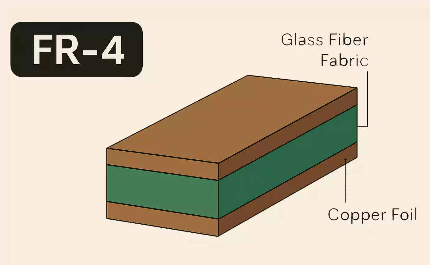
Within FR-4, you’ll find:
- Standard FR-4: Tg ≈ 135 °C, for low-cost devices.
- High-Tg FR-4: Tg ≈ 170 °C; better for lead-free soldering and multilayer applications.
- Low-Df FR-4: Improved for moderate high-speed applications.
- Halogen-free FR-4: For environmental compliance (RoHS, REACH).
FR-4 thickness commonly ranges from 0.4 mm to 3.2 mm, with copper weights from 0.5 oz to 3 oz per layer.
High-Frequency and High-Speed Materials
When your design operates above 1 GHz, the loss tangent and dielectric stability become dominant. FR-4 can’t maintain consistent impedance or low insertion loss at these frequencies.
That’s where PTFE (Teflon), Rogers, and LCP come in.
- PTFE offers the lowest Df (< 0.002) and excellent chemical stability.
- Rogers 4350B and 4003C combine PTFE-like performance with better manufacturability.
- LCP (Liquid Crystal Polymer) offers ultra-low moisture absorption and high dimensional stability, making it ideal for antennas and flexible RF modules.
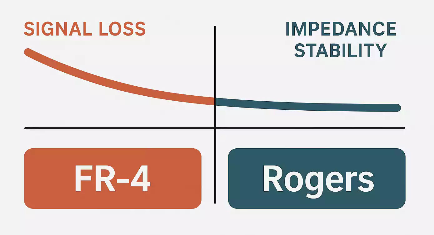
In many designs, engineers combine Rogers layers with FR-4 cores—a hybrid stackup that balances cost and performance.
High-Temperature and Flexible Materials
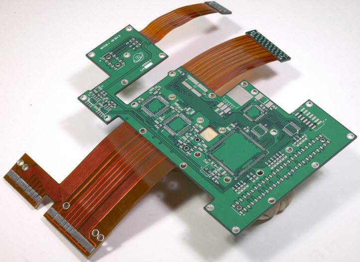
Polyimide substrates are used when a board must survive repeated temperature cycles or mechanical flexing.
- Tg > 250 °C, CTE < 50 ppm/°C, and stable dielectric properties make them perfect for aerospace, automotive under-hood, and rigid-flex designs.
- Polyimide can be used alone or laminated with FR-4 stiffeners in rigid-flex PCBs.
- Its flexibility and durability justify the higher price when reliability is critical.
Metal-Core and Ceramic for Heat Dissipation
When heat is the enemy, conductivity beats insulation.
Metal-core PCBs (MCPCBs) use an aluminium or copper baseplate to pull heat away from LEDs, power regulators, or motor drivers.
A thin dielectric layer (0.1–0.2 mm) isolates the circuit while maintaining thermal conductivity around 1–2 W/m·K—five times that of FR-4.
Ceramic PCBs (AlN or Al₂O₃) go even further, reaching 20–180 W/m·K with excellent rigidity and high-voltage isolation. They’re common in laser modules, RF power amplifiers, and aerospace electronics, where cost is secondary to performance.
Manufacturing and Stackup Considerations
Even the best material can fail if used incorrectly. Keep these points in mind:
| Dielectric thickness tolerance | ±10 % | Avoid over-constraining impedance—specify a range, not an exact number |
| Copper roughness | 1–3 µm | Choose smoother foil for high-speed layers |
| Drill aspect ratio | ≤ 10:1 | For thick boards, consider stacked vias |
| Press cycles | Up to 3 | Plan lamination sequence early |
| Tg vs. solder profile | Tg ≥ 30 °C above peak reflow | Prevent delamination |
Discuss your material choice with your PCB fabricator early. Some exotic laminates require special prepreg, plasma cleaning, or lower lamination pressures.
Common PCB Material Brands and Grades
The following brands are widely recognised and interchangeable in many cases:
| Isola | 370HR, FR408HR | High-speed FR-4 replacements |
| Ventec | VT-47, VT-901 | Lead-free, high-Tg, mid-loss |
| Rogers | 4350B, 4003C, 5880 | RF and microwave industry standard |
| Panasonic | Megtron 6 | Ultra-low loss, used in servers |
| Dupont | Pyralux AP, FR | Polyimide and flexible laminates |
Brand availability varies by region, so confirm with your supplier before finalising the stackup.
Cost and Availability
Material choice affects not only electrical behaviour but also leads to the total cost.
| FR-4 | 1× | Standard production |
| High-Tg FR-4 | 1.3× | Moderate cost, great reliability |
| Polyimide | 2–3× | Expensive but durable |
| Rogers / PTFE / LCP | 3–6× | For RF and microwave |
| Ceramic / Metal-core | 4–8× | Specialized applications |
To control cost:
- Use hybrid stackups (FR-4 + high-frequency layers only where needed).
- Order full panels to reduce material waste.
- Choose standard thicknesses and prepreg combinations stocked by your manufacturer.
FAQs
1. What is FR-4 PCB material?
A fibreglass-epoxy laminate that’s flame-retardant, low-cost, and ideal for most consumer and industrial electronics.
2. What types of PCB materials exist?
FR-4, high-Tg FR-4, Polyimide, PTFE (Teflon), Rogers, LCP, metal-core, ceramic, and CEM composites.
3. What are the main PCB material properties?
Dielectric constant (Dk), dissipation factor (Df), glass transition temperature (Tg), coefficient of thermal expansion (CTE), thermal conductivity, and density.
4. What is the typical PCB material density?
Around 1.8 g/cm³ for FR-4, 1.7 g/cm³ for Polyimide, 2.1 g/cm³ for PTFE, and 3.8 g/cm³ for ceramics. Metal cores range from 2.7 g/cm³ (aluminium) to 8.9 g/cm³ (copper).
5. Which material is best for high-speed or RF circuits?
Rogers 4350B/4003C or LCP. They offer low loss and stable dielectric performance across a wide frequency range.
Conclusion
Choosing the right PCB material is one of the most important steps in building a reliable and cost-effective circuit board. Each material—whether FR-4, Polyimide, Rogers, PTFE, or metal-core—offers a different balance of electrical performance, heat resistance, and mechanical strength. For most designs, high-Tg FR-4 delivers solid performance at a low cost, but high-speed or high-temperature projects benefit from advanced laminates with lower loss and better stability.

To get the best results, match the material to your application’s real needs—signal speed, power level. The right material choice not only improves signal integrity and heat management but also reduces production issues and extends product life.