In PCB manufacturing, the PCB drilling process is one of the most important fabrication stages. It directly affects hole wall quality, hole position accuracy, interlayer connection reliability, and the stability of downstream processes such as plating, imaging, and final assembly.
Different board types and quality needs require various PCB drilling methods. Manufacturers select approaches based on board thickness, aspect ratio, hole requirements, and machine limits.
This article explains the most common drilling methods used in PCB fabrication and outlines the standard PCB drilling process for double-sided and multilayer boards.
Common PCB Drilling Methods
Depending on the board type, product design, and quality requirements, several methods may be used in the PCB drilling process.
1. Single-Pass Drilling
Single-pass drilling means each hole is completed in one drilling operation. This is the most commonly used method in PCB drilling.
Characteristics
- Simple to operate
- High production efficiency
- Suitable for most standard PCB products
For boards with conventional thickness, normal hole sizes, and general quality requirements, single-pass drilling offers a good balance of efficiency and cost. That is why it remains the standard method in volume production.
2. Step Drilling
For thick PCBs and boards with stricter hole wall quality requirements, step drilling may be used. As high-aspect-ratio products become more common, this method is likely to gain wider use in PCB drilling.
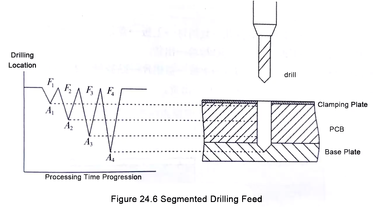
What Is Step Drilling?
In step drilling, a small hole is not drilled to full depth in one pass. Instead, the same drill bit advances in multiple stages until the hole is completed.
The main purpose is to improve chip evacuation during deep-hole drilling, reduce drill load, and improve hole wall quality.
Typical Applications
- Thick PCBs
- High-aspect-ratio holes
- Products with tight requirements for hole wall roughness and overall hole quality
Special Requirements for Step Drilling
This method places higher demands on both equipment and tooling:
- The drilling machine must have high spindle positioning accuracy.
- The machine must offer stable machining performance.
- The drill bit must be resistant to breakage.
Process Characteristics
According to the original process logic, the incremental movement and feed rate are typically set as:
- Travel increment: A1 > A2 > A3 ≥ A4
- Feed rate: F1 > F2 > F3 ≥ F4
Why These Settings Matter
As drilling depth increases, chip removal becomes more difficult, while drill loading and heat generation increase. For that reason:
- Larger increments and faster feed can be used in the early stages to improve efficiency.
- Smaller increments and lower feed rates are used in the later stages to improve chip evacuation.
- This helps reduce the risk of drill breakage.
- It also helps improve hole wall quality.
In other words, step drilling is not just drilling in several passes. It is a controlled deep-hole drilling strategy designed to improve overall PCB drilling stability.
3. Pilot Drilling
Pilot drilling is used when drilling large holes. A smaller drill bit is first used to make a guide hole, and then the larger drill bit is used to drill through the board.
Purpose of Pilot Drilling
The main purpose is to:
- Protect the machine spindle from damage.
- Improve drill guidance for large holes.
- Reduce the impact load when a large drill enters the board directly.
Typical Use Case
This method is mainly used for holes with an aspect ratio of 20 or greater.
However, it is not commonly used in general production.
Why It Is Not Common
For very high-aspect-ratio boards, pilot drilling may require a small-diameter drill with a longer flute length. When such a long-flute drill enters the board:
- The hole may become misaligned or slanted.
- The drill is more likely to break.
So, although pilot drilling can help guide the larger drill, it may also introduce new risks in high-aspect-ratio applications.
Use in Reaming Operations
Pilot drilling can also be used for reaming or hole enlargement. In these cases, the process requires stricter control of:
- Hole position accuracy
- Spindle runout
Otherwise, concentricity and final hole quality may be affected.
4. Front-and-Back Drilling
When the board thickness exceeds the normal drilling range, front-and-back drilling may be used.
How It Works
- First, drill approximately half the depth from one side.
- Then flip the board and drill through from the opposite side.
Purpose
This method is used for extra-thick boards or when drilling through from one side is impractical. Its advantages include:
- Reduced deep-hole drilling difficulty
- Better chip evacuation
- Lower risk of drill wandering or breakage
In essence, front-and-back drilling splits one difficult deep drilling operation into two shallower ones.
5. Flip Drilling
When the panel size exceeds the drilling machine's drilling range, flip drilling is required.
How It Works
- Drill approximately half of the holes along the length of the production panel.
- Then rotate or flip the panel.
- Drill the remaining holes from the opposite direction.
Typical Application
- Oversized PCB panels
- Panels longer than the machine’s available drilling travel
Key Control Points
The most important factor in flip drilling is maintaining accurate alignment before and after flipping the panel. This requires:
- Reliable repositioning
- Accurate program referencing
- High machine repeatability
Otherwise, a hole mismatch may occur in the overlap area.
6. Controlled-Depth Drilling
Controlled-depth drilling means drilling to a specified layer or depth in the board rather than drilling all the way through. This is an important special process within the broader PCB drilling process.
Main Applications
- PCB back drilling
- Blind holes that require depth control
Process Sequence
The correct process sequence is:
- Lamination first
- Drilling second
This means controlled-depth drilling is performed after lamination, not as part of standard through-hole drilling.
Equipment Capability
Most modern drilling machines already have controlled-depth drilling capability.
For applications such as PCB back drilling, depth accuracy is especially important because it directly affects the final electrical and structural result.
7. Slot Machining
In addition to round holes, PCB manufacturing often includes slotted holes or narrow slots. As a result, PCB slot machining is also an important part of some PCB fabrication projects.
Long Slot Machining
When the slot length is more than twice the drill diameter, the correct machining method is not simply continuous overlapping drilling. Instead, the spacing between adjacent drilled holes must be controlled properly.
This means a slot should not be treated as a chain of fully overlapping holes. Proper spacing is necessary to achieve better dimensional control and machining stability in PCB slot machining.
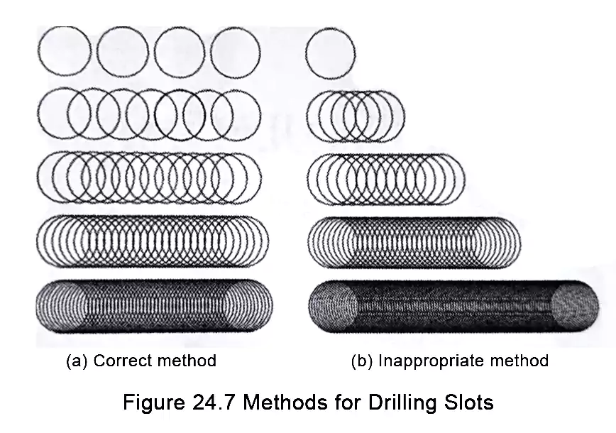
Short Slot Machining
When the slot length is:
- Less than 2 times the drill diameter
- But greater than 1.5 times the drill diameter
The machining error becomes larger, and special processing methods are required.
Why Short Slots Are More Difficult
These short slots fall between a standard round hole and a conventional long slot, which makes them harder to control. Problems may include:
- Greater dimensional error
- Poor shape consistency
- Irregular slot edges
- Lower process repeatability
As a result, short PCB slot machining is often more difficult than long slot machining.
PCB Drilling Process Flow
The PCB drilling process is not just a simple hole-making operation. It is a complete manufacturing process involving material preparation, drilling setup, inspection, and quality control.
The flow differs slightly depending on whether the board is double-sided or part of a multilayer PCB drilling job.
1. When Drilling Happens for Different PCB Types
- Single-sided and double-sided PCBs are typically drilled after panel cutting.
- Multilayer PCBs are drilled after lamination.
This distinction is important because holes in multilayer boards must align not only with the outer layers, but also with the internal layers for proper interconnection. That is why multilayer PCB drilling requires tighter control.
2. Five Basic Steps in the PCB Drilling Process
In general, the PCB drilling process can be divided into five basic stages:
- Incoming material inspection
- Preparation of drilling auxiliary materials
- Drilling
- Inspection
- Shipment
These five steps cover the workflow from incoming material verification to final quality release.
Double-Sided PCB Drilling Process Flow
The drilling process for double-sided PCBs is as follows:
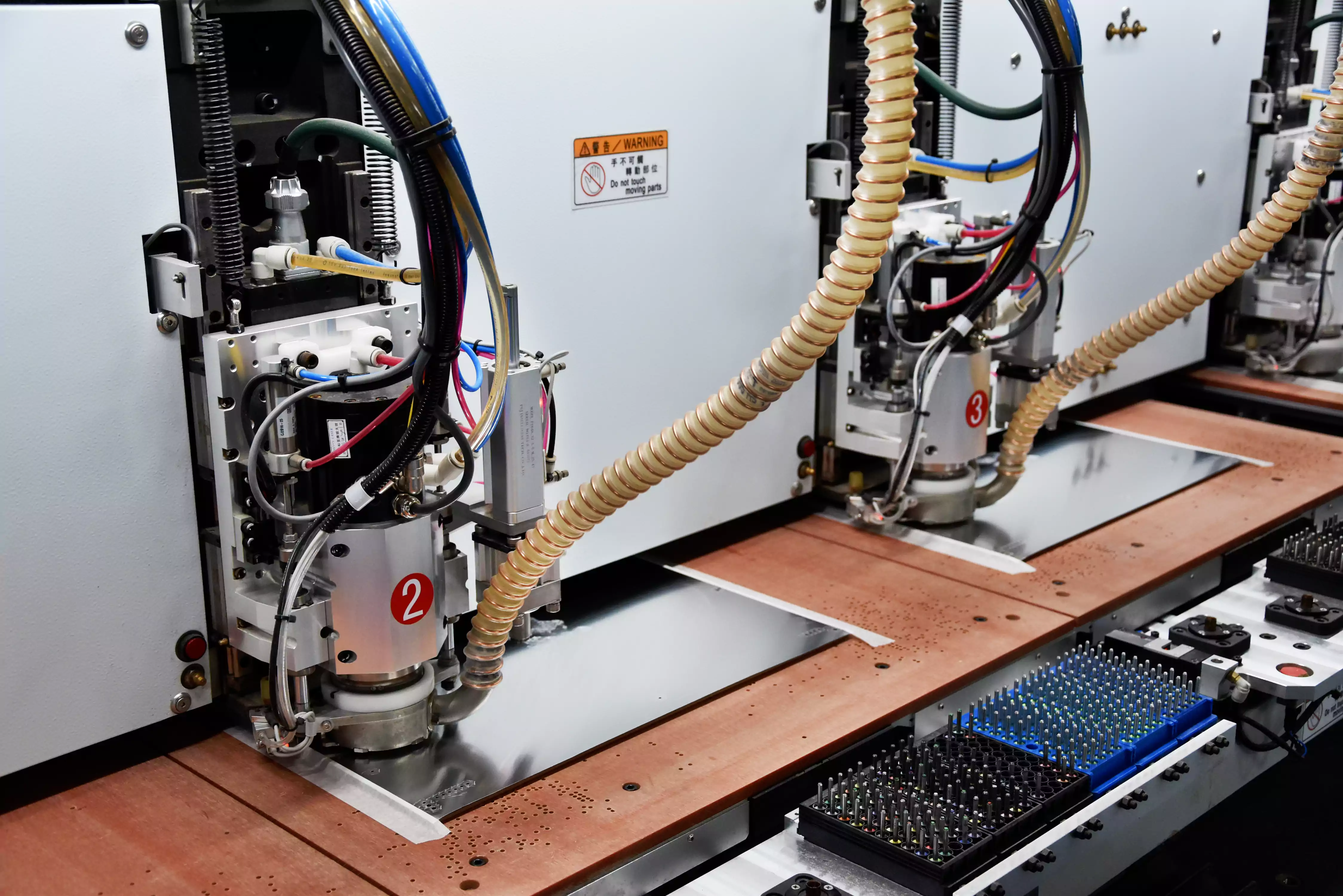
Place backup board → prepare tooling or position holes → insert locating pins → load panel → place aluminum entry sheet → apply tape → arrange drill bits → load program → set parameters → set zero point → drill → unload panel → deburr or polish → QC inspection → shipment.
1. Place Backup Board
A backup board, often made of phenolic material, is used as a support material to improve drilling stability and protect the board or machine during drilling.
2. Tooling Holes and Locating Pins
These are used to accurately position the panel and prevent hole-location errors during drilling.
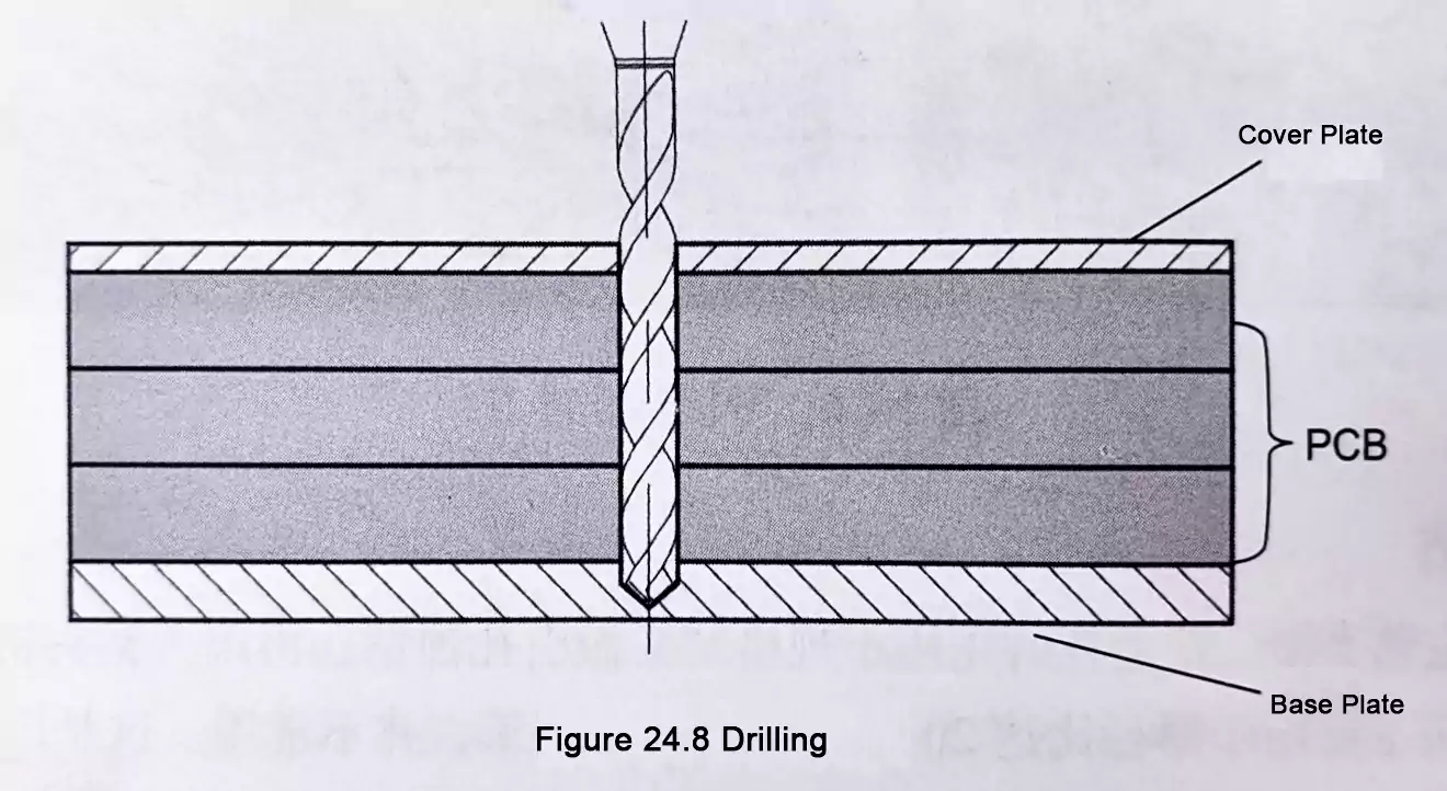
3. Load Panel, Place Aluminum Entry Sheet, and Apply Tape
These steps are part of the drilling material setup. Their functions typically include:
- Improving drill entry stability
- Supporting heat dissipation and chip removal
- Reducing burr formation
- Securing the panel during machining
4. Arrange Drill Bits
Drill bits are selected and arranged according to hole size requirements and drilling sequence.
5. Load Program, Set Parameters, and Set Zero Point
These are critical setup steps before actual drilling. They ensure:
- The correct drilling program is used.
- Parameters match the board material and hole dimensions.
- The machine datum is set correctly.
6. Drill
The machine drills the holes according to the programmed instructions.
7. Unload and Deburr
After drilling, the panel is unloaded, and any necessary deburring or surface cleanup is performed.
8. QC Inspection
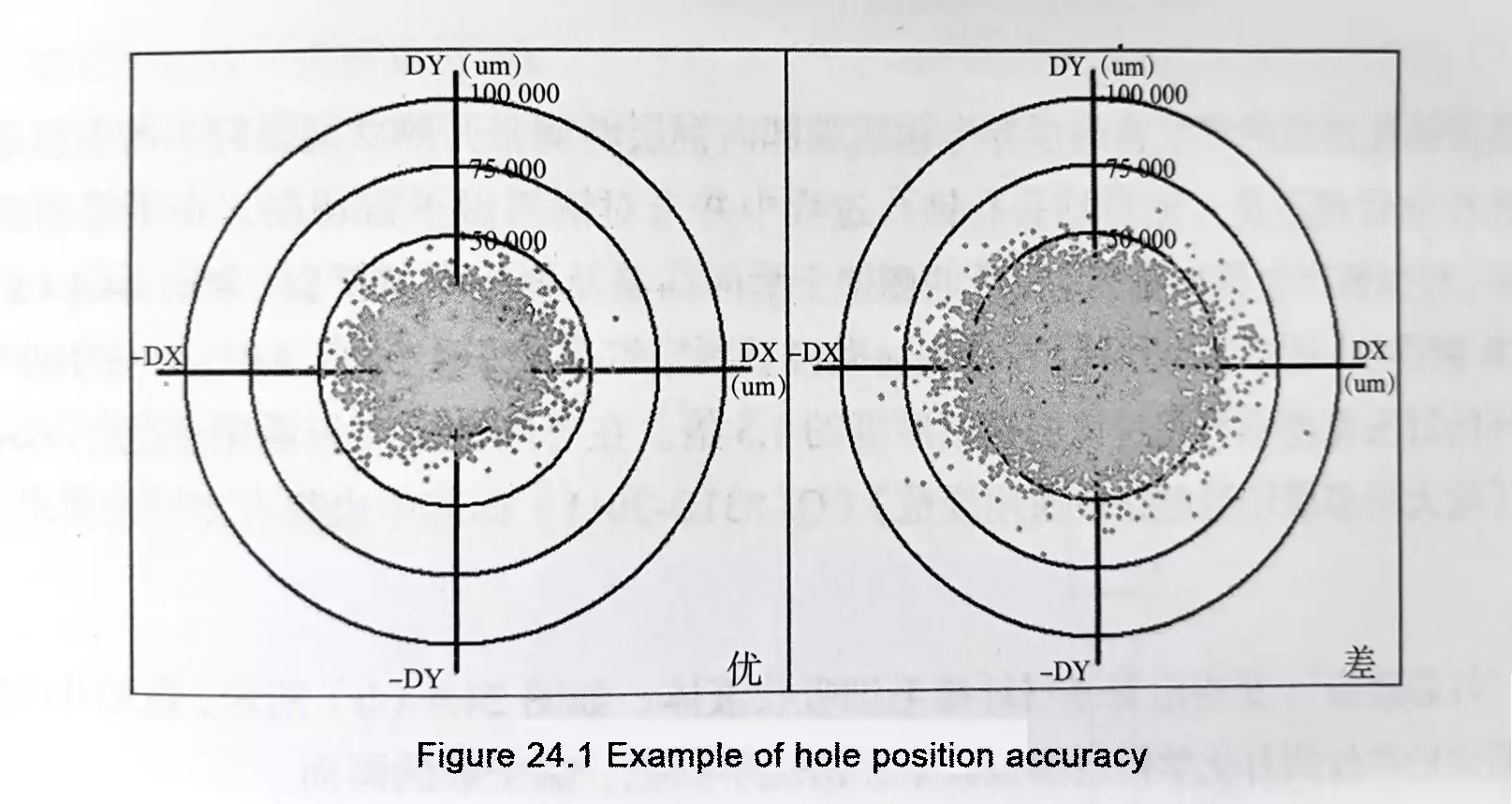
The holes are inspected for diameter, position accuracy, burrs, and hole wall quality.
9. Shipment
After passing inspection, the panels move to the next process or are released for shipment.
Multilayer PCB Drilling Process Flow
The process for multilayer PCB drilling is as follows:
Place backup board → insert locating pins → load panel → place aluminum entry sheet → apply tape → arrange drill bits → load program → set parameters → drill → unload panel → X-ray inspection → deburr or polish → QC inspection → shipment
Compared with double-sided PCB drilling, the multilayer PCB drilling process has several important differences.
- Multilayer Boards Are Drilled After Lamination
- X-Ray Inspection Is Added
- Multilayer PCBs Require Higher Drilling Accuracy
FAQ About PCB Drilling Process
What is the PCB drilling process?
The PCB drilling process is the manufacturing stage in which holes or slots are created in a PCB panel for electrical interconnection, component mounting, positioning, or special structural functions. It also includes setup, auxiliary materials, inspection, and quality control.
What is the difference between PCB drilling and multilayer PCB drilling?
Standard PCB drilling generally refers to hole-making on any type of board, while multilayer PCB drilling specifically involves drilling after lamination and requires tighter alignment control because the holes must connect correctly with the internal layers.
What is PCB back drilling used for?
PCB back drilling is used to remove unwanted via stubs or to control drilling depth to a specified layer. It is commonly treated as a form of controlled-depth drilling.
Why is controlled-depth drilling difficult?
Controlled-depth drilling is sensitive to board thickness variation, layer tolerance, drill wear, and machine control accuracy. Even when equipment supports the function, maintaining consistent depth remains a process challenge.
What is PCB slot machining?
PCB slot machining refers to the processing of slotted holes or narrow slots in a PCB. Depending on slot length and geometry, the machining method may differ from standard round-hole drilling.
Conclusion
The PCB drilling process involves more than simply making holes. It includes multiple drilling methods selected according to board thickness, hole structure, size, and quality requirements.
Methods such as single-pass drilling, step drilling, controlled-depth drilling, PCB back drilling, and PCB slot machining each serve different manufacturing needs. In multilayer PCB production, drilling accuracy is especially critical because it directly affects inner-layer alignment, hole quality, and final reliability.
A clear understanding of the PCB drilling process helps manufacturers improve process control, maintain hole quality, and ensure reliable finished boards.