In PCB manufacturing, hole quality impacts electrical reliability, structural strength, and multilayer registration. Hole structures play roles in interlayer connection, component mounting, and alignment throughout manufacturing.
Common hole-making methods include mechanical drilling, laser drilling, and punching, with mechanical drilling still being the primary process used in PCB fabrication. Understanding PCB drilling fundamentals and the different PCB hole types is an important step in learning PCB manufacturing.
Why PCB Drilling Matters in PCB Manufacturing
Holes are one of the most important structural features in a PCB, and the quality of PCB drilling directly affects several key areas:
1. Electrical connection reliability
For plated holes in particular, the quality of the metalized hole wall determines whether conductive patterns on different layers can be reliably connected.
2. Component mounting accuracy and structural integrity
Many holes serve not only electrical purposes, but also mechanical functions such as component insertion, positioning, fastening, and assembly support.
3. Stability of downstream processes
Hole location accuracy, diameter consistency, and alignment with internal layers all affect subsequent processes such as plating, imaging, lamination, testing, and routing.
4. Special process functions
For example, backdrilled holes help reduce signal interference in high-speed designs, impedance test holes support electrical verification, and coupon cross-section holes are used for quality analysis. Positioning holes and tooling holes support the manufacturing process itself.
Main PCB Drilling and Hole Fabrication Methods
PCB holes can be created by several different processes. The most common include:
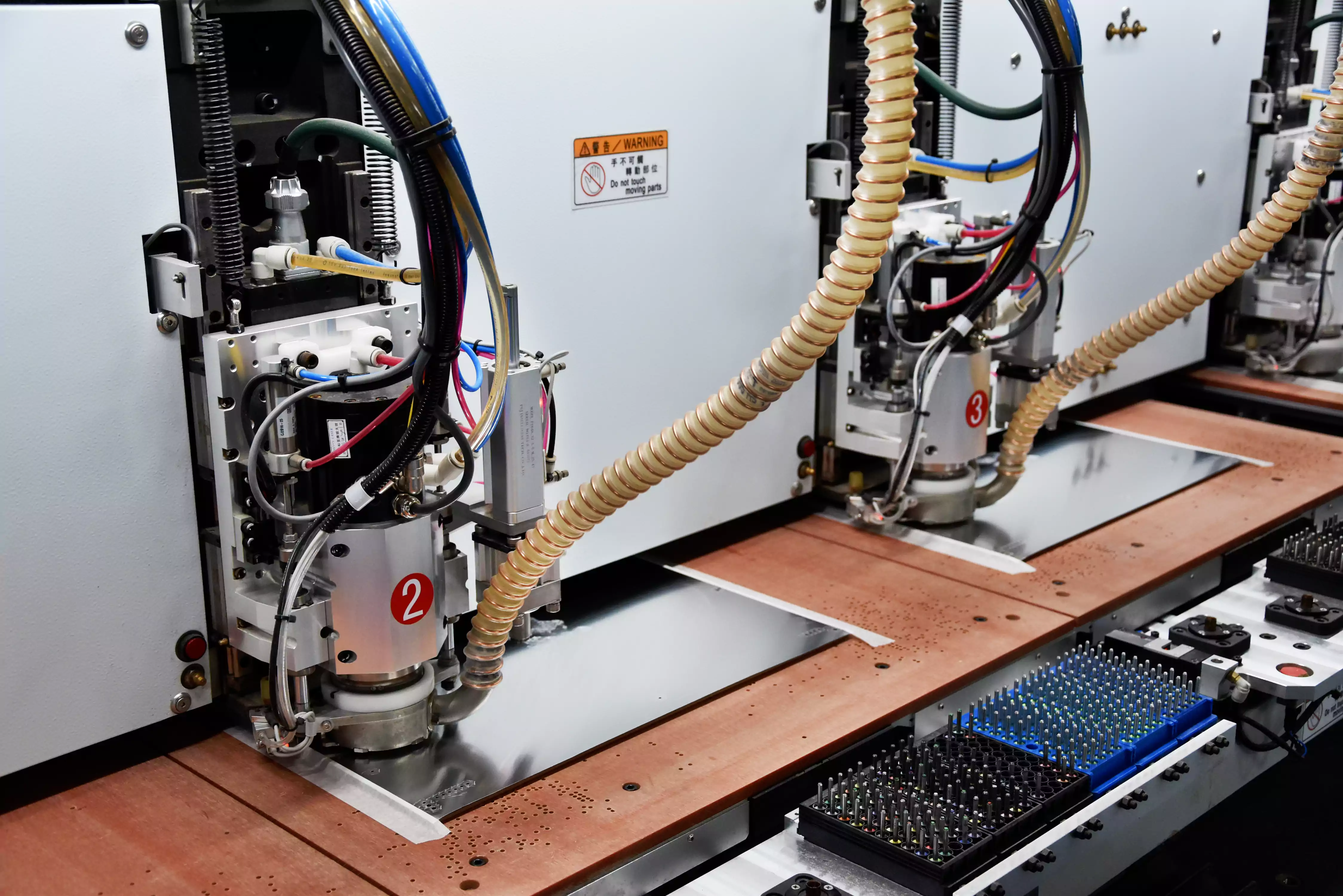
1. Mechanical Drilling
Mechanical drilling is still the most widely used PCB drilling method in PCB manufacturing. It is suitable for a large number of standard holes, especially through holes, component holes, vias, and many process-related functional holes.
2. Laser Drilling
Laser drilling is typically better suited for very small holes and fine-pitch high-density interconnect structures.
3. Punching
Punching is another hole-fabrication method, though its use is more limited and depends on the product's structure and manufacturing requirements.
From a practical production standpoint, mechanical PCB drilling remains the core hole fabrication process. As a result, the related tooling and process system—including drill bits, drilling machines, entry sheets, backup boards, and drilling defect control—plays a central role in PCB manufacturing.
Basic Evaluation and Classification of PCB Hole Types
In PCB manufacturing, PCB hole types can first be classified based on whether they participate in electrical interconnection.
1. Classification by Electrical Function
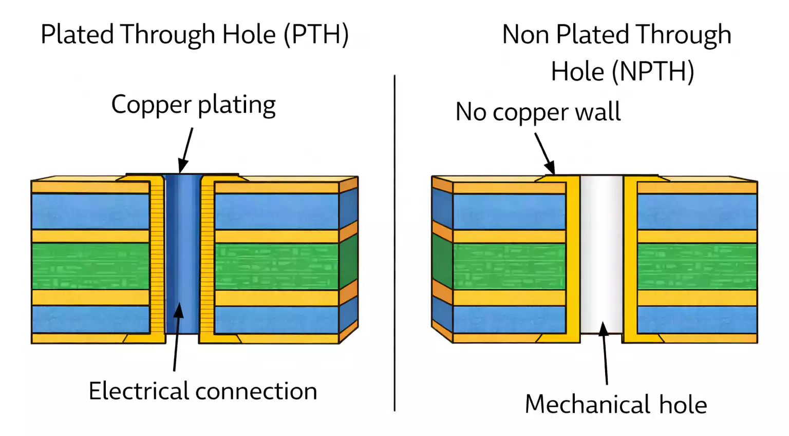
Plated Through Hole (PTH)
A plated-through hole is a hole whose walls are coated with metal. This type of hole can provide an electrical interconnection between:
- Inner layers
- Outer layers
- Inner and outer layers
In other words, the core function of a PTH is to electrically connect conductive patterns on different layers.
It is important to note that the final finished hole size is determined not only by the drill diameter, but also by the thickness of the plated metal on the hole wall. Therefore, the finished hole size depends on two factors:
- The original drilled hole size
- The thickness of the plated metal layer
Non-Plated Through Hole (NPTH)
A non-plated through hole does not participate in electrical interconnection. In other words, the whole wall is not used as a conductive path.
These holes typically serve functions such as:
- Positioning
- Mounting
- Tooling
- Foolproofing
- Mechanical fastening
- Process support
2. Classification by Hole Depth and Layer Penetration
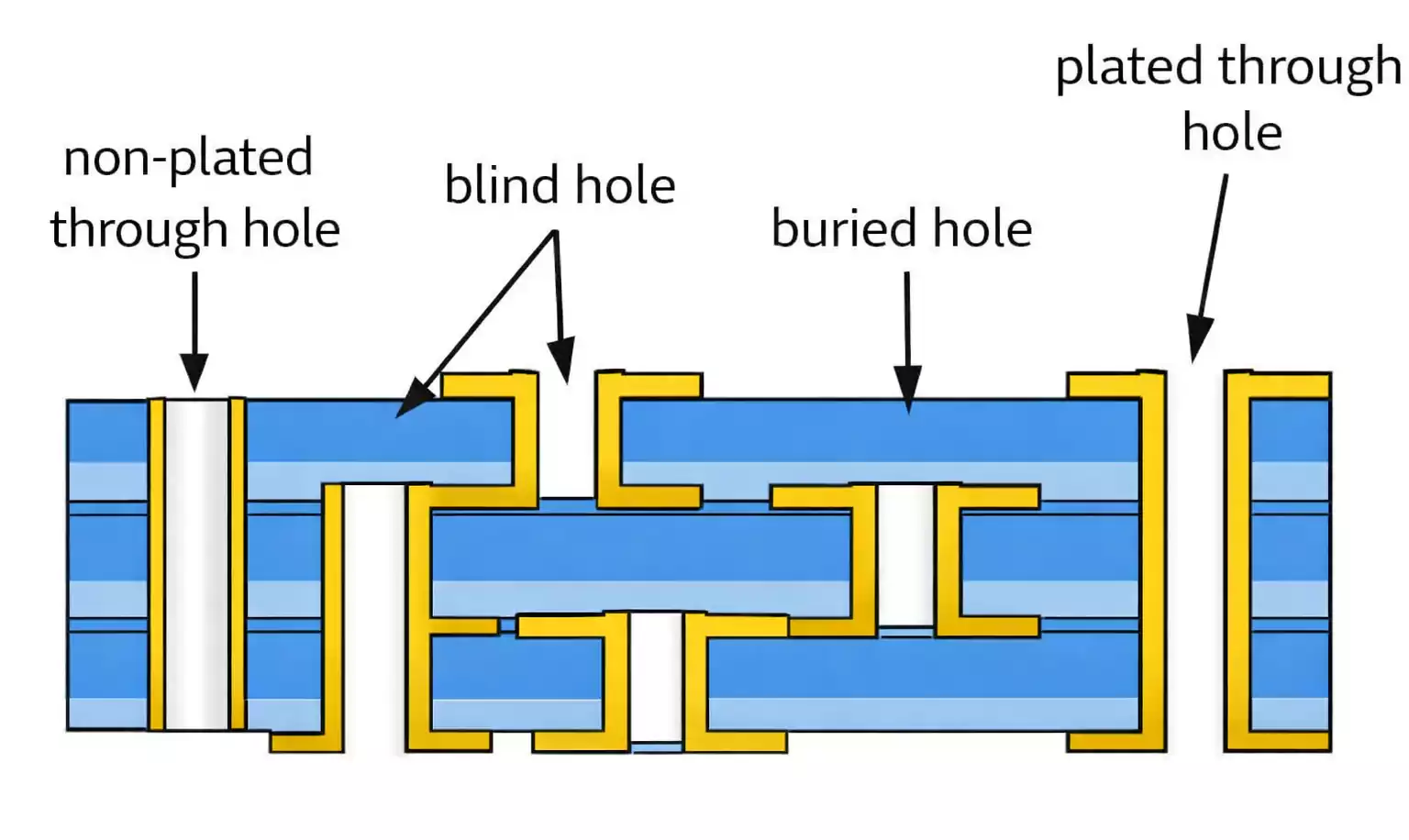
Based on how far a hole extends through the PCB, PCB hole types can be divided into:
- Through holes
- Buried holes
- Blind holes
Through Hole
A through hole extends through the entire PCB. It may be used for electrical connection, component mounting, or positioning.
Through holes generally fall into two main categories:
(1) Component Hole
This type of hole is used for inserting component leads, pins, or wires, while also providing:
- Mechanical attachment of the component to the PCB
- Electrical connection between the component and the circuit
(2) Via
This is a plated hole used solely for interlayer interconnection. It is not used for inserting component leads or other reinforcing materials.
(3) Two Main Purposes of Drilling Through Holes
In PCB fabrication, drilling through holes generally serves two major purposes:
- First, to create an opening through the board.
This allows later manufacturing steps to form electrical connections between the top and bottom layers and the internal circuit layers. - Second, to maintain structural integrity and positional accuracy for component installation.
Through holes also help ensure that mounted components are securely positioned and properly aligned.
Buried Hole
A buried hole is a conductive hole that does not extend to the outer surface of the PCB. It exists only between internal layers and is not visible from the outside.
Blind Hole
A blind hole is a conductive hole that extends from only one outer surface of the PCB to one or more internal layers, without passing through the entire board thickness.
Common PCB Hole Types Used for Functional Purposes
In actual PCB production, not all holes are used only for electrical interconnection or component mounting. Depending on the product design and factory process requirements, many auxiliary PCB hole types are also used for positioning, analysis, testing, identification, assembly, and process control.
Common PCB Hole Types include:
1. Slot Hole
A slot hole is not a single round hole. It is typically formed in one of two ways:
- Automatically converted into a drill program into a series of overlapping drilled holes.
- Machined by routing or milling
Slot holes are commonly used for:
- Connector installation
- Card-edge or tab-type mechanical mounting
- Components or connectors with non-circular lead shapes
In short, a slot hole is a hole form used to meet non-round mounting requirements.
2. Backdrill Hole
A backdrill hole is created by drilling a controlled-depth hole into an already plated through hole, using a larger drill diameter than the original plated hole.
Its main functions are:
- Removing unused via stubs
- Interrupting unnecessary conductive remnants
- Reducing interference during signal transmission
For this reason, backdrilling is commonly used in high-speed and high-frequency PCB designs to improve signal integrity.
3. Positioning Hole
Positioning holes are typically located on the top or bottom of the PCB, usually in sets of three or four. Other holes on the panel are referenced to these holes, so they are also called:
- Target holes
- Fiducial positioning holes
Before drilling, these reference holes are typically created using optical punching or X-ray target drilling equipment. They serve to establish the drilling datum, enable pin-based location and clamping, and ensure accurate hole registration.
4. Inner-Layer Registration Hole
Inner-layer registration holes are usually located near the edge of multilayer boards. They are mainly used to:
- Determine whether internal layer misregistration exists before drilling the production pattern.
- Decide whether the drilling program needs compensation or adjustment.
In other words, these holes are used to verify multilayer alignment before formal drilling begins, which is especially important for high-layer-count and high-precision PCBs.
5. Code Hole
Code holes are typically arranged in a row near one side of the panel and are used to identify production-related information, such as:
- Product model
- Machine used
- Operator code
Today, many factories have replaced this method with laser marking.
6. Mounting Hole
A mounting hole is a relatively large hole in the PCB used to:
- Fasten the PCB to a chassis, bracket, frame, or other support structure.
This type of hole mainly serves mechanical assembly needs and is closely related to the final product structure.
7. Tail Hole
Tail holes are a set of holes of different sizes located along the edge of the production panel. Their purpose is to:
- Verify that the drill diameter remains correct throughout the drill bit's use.
Tail holes can be used as a drill-size verification or process-identification feature.
8. Coupon Cross-Section Hole
A coupon cross-section hole is a plated hole intended for microsection analysis. Its significance is that it can:
- Reveal the quality of the hole during cross-sectional inspection.
For example, cross-sectional analysis can be used to evaluate hole-wall plating, copper thickness, and layer bonding conditions. This makes such holes important for quality control.
9. Impedance Test Hole
An impedance test hole is a plated hole used for PCB impedance testing.
It supports impedance verification and process control and is commonly used in high-speed, high-frequency PCB products.
10. Foolproof Hole
A foolproof hole is generally a non-plated hole used to:
- Prevent the board from being loaded in the wrong orientation.
- Avoid direction-related processing errors.
- Assist in positioning in operations such as routing or imaging.
11. Tooling Hole
A tooling hole is generally a non-plated hole used in conjunction with tooling for related process steps.
Its functions may include positioning, clamping, transfer, or fixture support during manufacturing.
12. Rivet Hole
A rivet hole is a non-plated hole used during multilayer lamination to fix core layers and prepregs together with rivets.
During drilling, the rivet location must be drilled through in order to:
- Prevent trapped air from remaining at the rivet position.
- Avoid later defects such as blistering or board blow-up during subsequent processes.
So, a rivet hole is not just a fastening feature; it is also directly related to the quality of multilayer lamination.
Understanding the Relationship Between Different PCB Hole Types
Many beginners confuse these terms, but they actually belong to two different classification dimensions.
1. Whether the Hole Participates in Electrical Interconnection
- PTH: participates in electrical interconnection
- NPTH: does not participate in electrical interconnection
2. How Far the Hole Extends Through the Board
- Through hole: extends through the entire board.
- Blind hole: extends from one surface only
- Buried hole: does not reach the outer surface
What Should Be Considered in PCB Drilling and Hole Design?
As this discussion shows, a PCB hole is not just a simple opening in the board. It can simultaneously carry electrical, mechanical, process, testing, and quality-control functions.
In actual design and manufacturing, at least the following points should be considered:
1. Clearly Define Whether the Hole Has an Electrical Function
This is the basis for distinguishing PTH from NPTH and directly determines whether hole wall metallization is required.
2. Clearly Define Whether the Hole Goes Through the Entire Board
This determines whether the hole is a through hole, blind hole, or buried hole, and it also affects fabrication difficulty and process selection.
3. Do Not Overlook Auxiliary Functional Holes
Many production issues are not caused by the interconnect holes themselves, but by poorly designed positioning, registration, testing, lamination, or foolproof features.
4. Understand the Role of Each Hole in the Entire Process Chain
The same hole may affect multiple aspects of manufacturing, including:
- Drilling accuracy
- Plating quality
- Layer registration
- Component assembly
- Signal integrity
- Quality analysis
- Mass production consistency
Conclusion
PCB holes connect design intent with real-world fabrication and assembly. They’re typically classified by electrical function—PTH (plated) vs. NPTH (non-plated)—and by depth—through, blind, and buried holes.
In production, PCB drilling remains the primary method for creating holes. From an engineering standpoint, correctly defining hole type and purpose is critical to ensure reliable interconnects, stable manufacturability, and consistent quality.