

As PCB operating frequencies shift from the MHz to the GHz range, design priorities change.
Copper foil is no longer just a conductive layer — its surface texture directly affects how signals travel and has become a key source of high-speed signal loss.
This article explains, from an engineering perspective, how copper foil roughness affects signal attenuation in high-speed PCBs.
1. Skin Effect – High-Frequency Currents Flow on the Surface
When frequency increases, electrical current tends to flow only near the conductor surface.
This phenomenon is called the skin effect.
The skin depth decreases as frequency increases, and at frequencies above 1 GHz, it is close to the average roughness of 0.5 oz copper foil on the shiny side.

This means that when the surface roughness of a copper surface is on the same order as the skin depth, the surface profile is no longer a microscopic detail — it directly influences signal transmission.
2. Why Roughness Adds Extra Loss
Signal loss in high-speed PCBs comes mainly from two sources:
- Dielectric loss
- Conductor loss
Conductor loss is not only caused by the metal’s resistance but also by scattering loss from the surface roughness.
A rough surface forces the current to follow a longer, more uneven path, increasing resistance and energy loss.
This effect grows rapidly as frequency increases.
3. Test Results – Small Difference at Low Frequency, Big at High Frequency

Studies on different types of copper foil show:
- At around 1 GHz, the loss differences between foils with various roughness levels are small.
- At higher frequencies, the difference grows quickly.
- The rougher the surface, the greater the signal attenuation.
That is why copper roughness, often ignored in low-speed designs, becomes a serious concern in high-speed and RF applications.

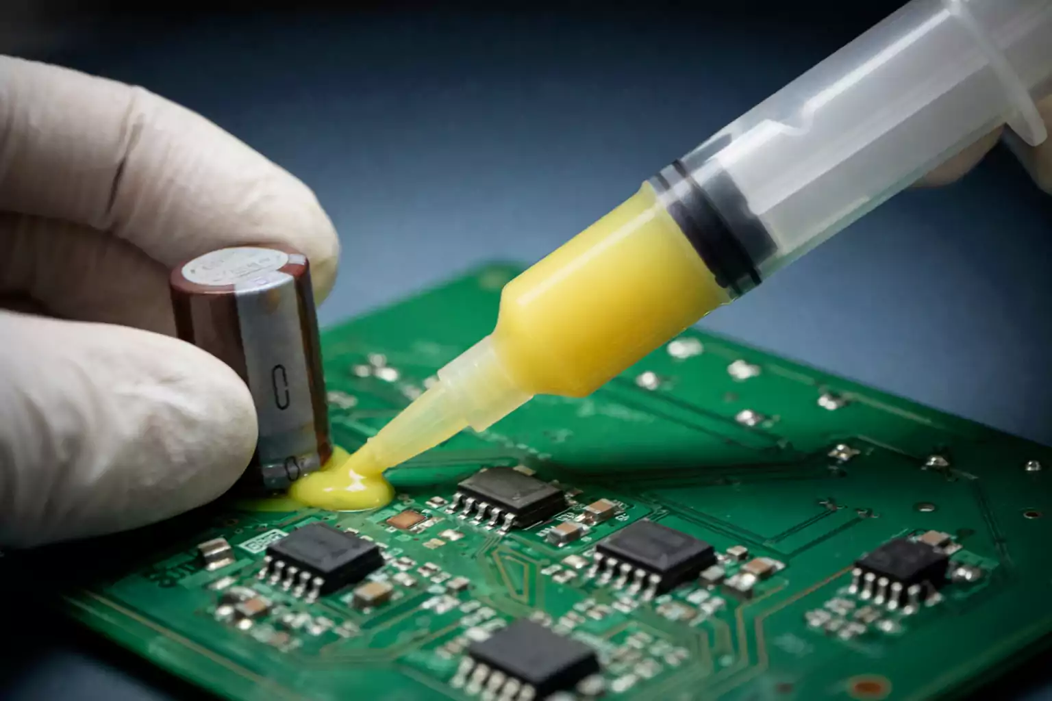
4. Manufacturing Impact – Brown Oxide Is Not “Free”
In PCB manufacturing, the brown oxide process roughens the copper surface using oxide or oxide-replacement chemistry to improve inner-layer adhesion.
Test comparisons at 1 GHz show:
- Smoother samples: Df ≈ 0.021
- Rougher samples: Df ≈ 0.026

These results show that while surface roughening improves bonding strength, the added roughness can become a major source of signal loss in high-speed designs.
5. Engineering Takeaways – Match Copper Foil to Signal Integrity
At GHz-level speeds or in RF applications, copper foil selection and surface treatment must align with signal-integrity requirements.
Many designers now choose:
- Low-profile copper foil
- Ultra-low-profile copper foil
- Reverse-treated (RTF) copper foil
These foils help maintain good reliability while minimising insertion loss and signal attenuation.
Conclusion
In modern high-speed PCB design, copper foil has evolved from a background material to an active factor that shapes signal integrity.
Understanding and controlling copper surface roughness is a key step toward reliable performance in the GHz era.
