When examining the internals of any electronic device—whether a computer motherboard, an LED controller, or an industrial sensor—the presence of connectors is a universal constant.
They link PCBs together, carry power and signals, and make devices modular and easy to assemble.
This guide focuses on PCB connectors: what they are, their core types (Board-to-Board, Wire-to-Board, I/O), edge connector roles, and how to identify the correct choice for your design.
What Is a PCB Connector?
A PCB connector is an electromechanical interface mounted on a printed circuit board that lets two circuits connect without soldering them permanently.
It transfers power, data, or both between boards, cables, or external devices.
Instead of soldering wires directly to the board, connectors create a plug-and-play interface — you can insert, remove, or replace modules quickly.
This saves assembly time, simplifies testing, and allows upgrades or repairs later.
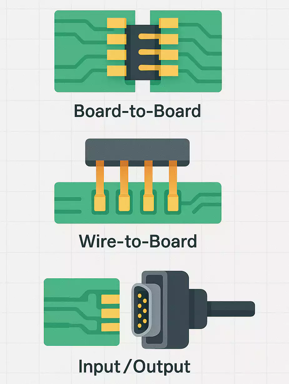
Three Main PCB Connectors Styles
1. Board-to-Board (BTB)
These connectors directly connect two circuit boards, typically within a single product.
You’ll find them in smartphones, routers, automotive modules, and industrial controllers.
BTB connectors come in several configurations:
- Parallel (mezzanine or stacking): two boards face each other and are stacked vertically.
- Right-angle (orthogonal): one board stands upright to the other, forming an L-shape.
- Coplanar or end-to-end: boards line up horizontally, often used in long backplanes.
Key parameters for high-speed designs include stacking height, alignment accuracy, and signal integrity.
2. Wire-to-Board (WTB)
WTB connectors link cables to a PCB.
They are everywhere — in fans, sensors, motors, battery packs, and control panels.
A typical WTB assembly includes a crimped or soldered terminal on the wire, a housing, and a header soldered to the PCB.
They handle flexible movement and allow quick field connections.
When choosing WTB parts, check current rating, locking feature, and orientation (vertical or right-angle).
3. I/O (Input-Output) Connectors
These connect the PCB to external devices or networks.
Common examples include USB, HDMI, RJ45 Ethernet, coaxial, audio jacks, and optical ports.
They provide both electrical and mechanical interfaces for communication or charging.
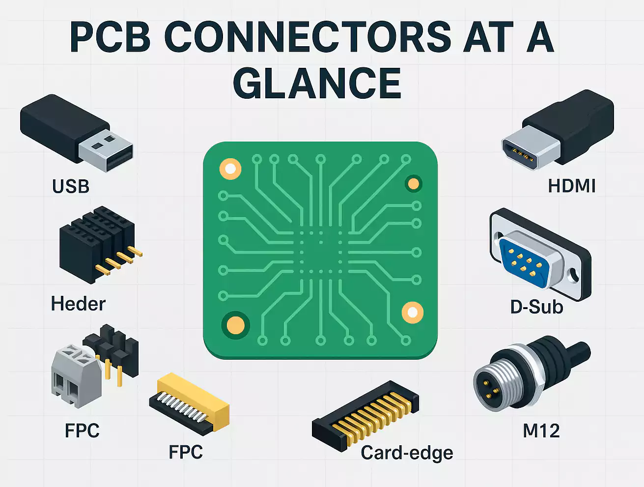
Popular PCB Connectors Types
The electronics world uses hundreds of connector families.
Below are the most common ones, along with what makes each special.
PCB Edge Connector (Gold Finger or Card Edge)
An edge connector uses the plated edge of the PCB itself as the male contact.
The mating socket or slot on the other board holds it firmly, just like how a PCIe or M.2 card plugs into a motherboard.
Key advantages include high pin density and low cost because no separate male connector is required.
- Simple assembly and easy replacement.
- Suitable for high-speed digital buses.
Typical applications include PC expansion cards, servers, LED strips, and backplane systems.
Mezzanine / Stacking Connectors (BTB)
Used for compact, multi-board assemblies where vertical space matters.
You’ll find them between logic and interface boards or daughtercards.
They support differential signaling and can handle gigabit-level speeds.
Pay attention to stack height, alignment pins, and ground shielding when designing for high-speed lines.
Headers and Sockets (Pin and Female Headers)
Probably the most familiar connector in prototyping and low-speed electronics.
They consist of rows of pins (male header) and matching receptacles (female header).
Common pitch values are 2.54 mm, 1.27 mm, and 1.0 mm.
They are cheap, simple, and reliable for development boards or jumper cables.
Straight headers connect parallel boards; right-angle versions connect perpendicular boards.
They can even form a permanent “hard stack” by soldering both ends.
FPC/FFC Connectors
Flexible Printed Cable (FPC) and Flat Flexible Cable (FFC) connectors are designed for thin ribbon cables.
They are widely used in laptops, displays, and cameras.
These connectors use a ZIF (Zero Insertion Force) or LIF (Low Insertion Force) latch to secure the ribbon.
Designers should note insertion direction (top or bottom contact), bend radius, and number of mating cycles.
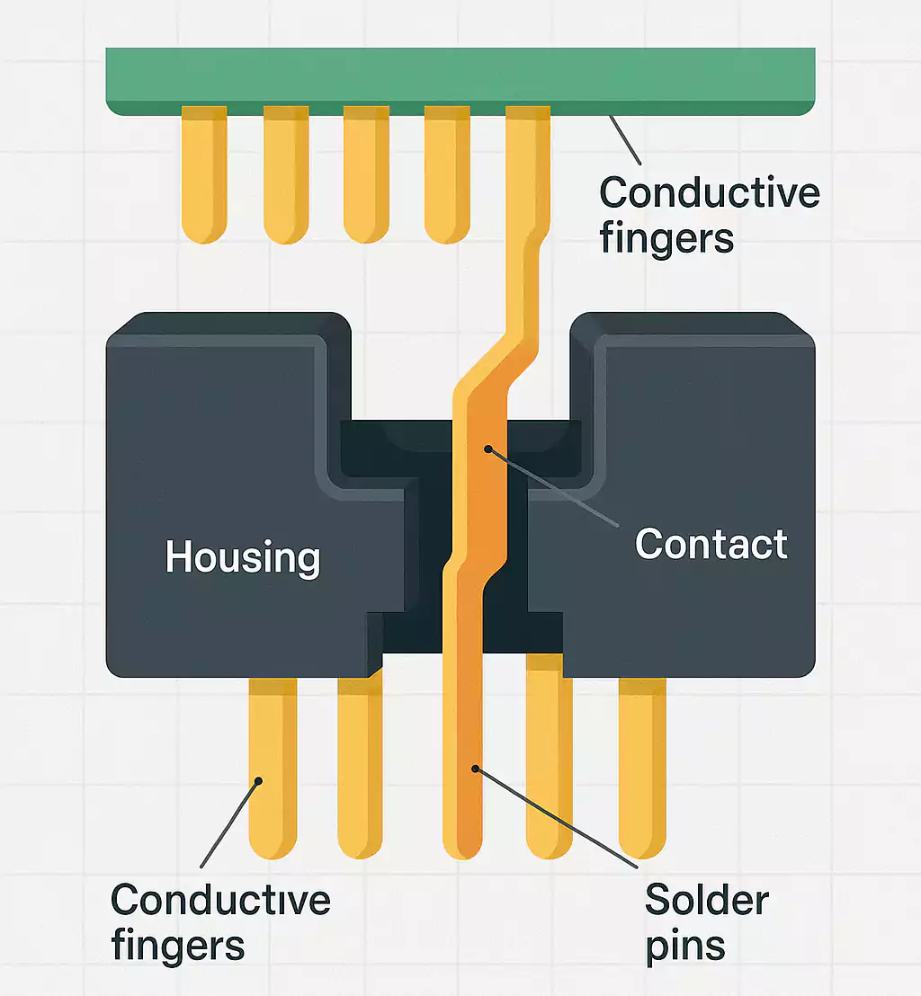
Terminal Blocks (Screw or Spring Type)
Terminal blocks are also called PCB board connectors in industrial and power applications.
They allow field wiring directly onto the board using screws or spring clamps.
- Screw type: classic, robust, easy to reuse.
- Spring or lever type: tool-free and faster for production lines.
They handle high current and larger wire gauges.
Look for pitch size, voltage rating, and mounting style (through-hole or SMT).
Circular Connectors (M12, M8, etc.)
Used in harsh or outdoor environments, circular connectors such as M12 are sealed to IP65-IP68 ratings.
Each code (A, D, X, L, T…) defines a specific pinout and use case, such as power, Ethernet, or sensor signals.
Their screw or bayonet locks resist vibration, making them ideal for industrial automation and robotics.
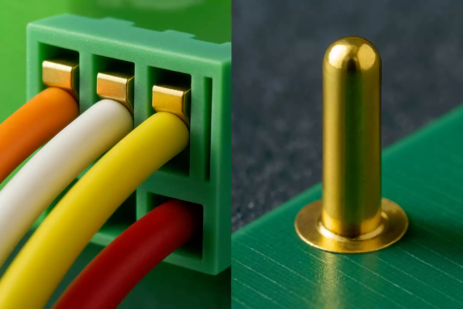
Pogo / Spring-Loaded Connectors
These connectors use spring pins to create temporary or tolerant contacts.
They compensate for small alignment errors and mechanical movement.
Typical uses: battery charging cradles, test fixtures, and modular handheld devices.
Important parameters: travel distance, spring force, and plating type (gold over nickel for low wear).
Three-Step Selection Method
Many hardware engineers use this 3-step method:
Start with voltage, current, and signal type.
For example:
- A 4-pin power connector may need 5 A per pin.
- A high-speed differential pair may require controlled impedance.
Also note how many contacts you need and whether they carry mixed signals (power + data).
2. Consider Mechanical and Assembly Factors
- Mounting style: through-hole (stronger) vs. SMT (smaller).
- Orientation: vertical, right-angle, stacking height.
- Locking and polarization: prevent reverse mating and vibration loosening.
- Mating cycles: how many times it will be plugged in and out.
If space is tight, low-profile mezzanine or FFC connectors work well.
3. Check Environmental and Reliability Needs
- Operating temperature range.
- Resistance to dust, moisture, and shock (IP rating).
- Flame retardancy or UL safety ratings.
- Expected lifespan or maintenance interval.
Selecting connectors with proper plating and sealing ensures your product survives its environment.
Structure and Material Basics
1. Pitch and Stack Height
Pitch (the distance between contacts) defines density and current capacity.
Fine-pitch BTB parts (0.4–0.5 mm) save space but require precise PCB alignment and reflow control.
Stack height influences trace length, impedance, and airflow inside the product.
2. Contact Plating
The metal finish affects both performance and cost:
- Gold: best corrosion resistance and low contact resistance; ideal for signal connectors.
- Tin: cheaper, suitable for power or low-cycle uses.
- Nickel underlayer: common base for wear protection.
3. Termination Methods
- Through-hole soldering (THT): strong mechanical joints.
- Surface-mount (SMT): compact, reflow-compatible.
- Crimp or IDC: for wire harnesses.
- Press-fit: no solder, often used in backplanes.
Each method trades off assembly speed, cost, and repairability.
Where Each Connector Type Fits Best
Different connector families suit different application areas:
1. High-Speed Computing & Communication
Use edge connectors or high-speed BTB models.
They provide controlled impedance and shielding for PCIe, SATA, or network signals.
2. Industrial Control & Power
Choose terminal blocks, M12 circular connectors, or locking WTB types.
They tolerate higher current and vibration.
3. Consumer Electronics & Prototyping
Opt for headers, sockets, and FPC/FFC connectors.
They’re cost-effective and fit compact housings.
4. Testing and Charging
Use pogo pins or spring contacts where repeated mating or tight mechanical tolerances are required.
FAQ
1. What is a PCB connector?
A component that provides a removable electrical interface between a printed circuit board and another board, cable, or device.
2. How do you connect two PCBs together?
You can use board-to-board connectors such as stacking (mezzanine), right-angle, or coplanar types.
For simple prototypes, soldered pin headers can make a fixed bridge.
For modular systems, edge connectors or backplanes are common.
3. What are the different types of board connectors?
The main families are:
- Board-to-Board (BTB)
- Wire-to-Board (WTB)
- I/O (external) connectors
Specialized types include edge connectors, FPC/FFC connectors, terminal blocks, circular connectors, and pogo pin connectors.
4. What is a PCB edge connector used for?
It connects daughter cards, memory modules, or LED strips to a main board.
Edge connectors are valued for their high pin density and low cost.
5. How do I choose a 4-pin PCB connector?
Check the current and voltage per pin, required locking method, pin spacing, and mating durability.
For power, pick larger pitch and tin-plated contacts; for signals, smaller pitch and gold plating work better.

Conclusion
PCB connectors are fundamental components that influence how a product is assembled, tested, and maintained.
By understanding the three main connection styles—BTB, WTB, and I/O—and the most common types—edge, FPC, terminal block, and pogo pin —you can make smarter design choices.
Selecting the right connector streamlines assembly, increases reliability, and supports future upgrades.