The real foundation of a PCB is its base material — the layer that supports copper and defines the board’s electrical, thermal, and mechanical performance. Understanding PCB board material helps you make the right decision for signal speed, heat dissipation, and reliability.
What Are PCB Boards Made Of?
Every PCB has a few main parts:
- Copper foil – the conductive layer that carries electrical signals.
- Base substrate (core or laminate) – the insulating layer that supports the copper and determines most of the board’s physical properties.
- Solder mask – the green (or other colour) coating that protects copper.
- Silkscreen – printed text or markings on the surface.
Among these, the substrate material is the most critical. It defines how the PCB behaves under heat, electrical stress, or mechanical bending.
Common PCB Board Material Families
FR-4 (Glass-Epoxy Laminate)
FR-4 is the standard material for most PCBs. It’s made from woven glass fibre cloth impregnated with epoxy resin.
- Typical properties: Dk ≈ 3.8–4.8, Df ≈ 0.009–0.02, Tg ≈ 130–180 °C.
- Advantages: Low cost, easy to process, mechanically strong, and widely available.
- Limitations: Signal loss increases at very high frequencies; glass weave can cause impedance variations in high-speed designs.
- Applications: Consumer electronics, industrial controls, and automotive modules.
High-Tg FR-4 versions are available for lead-free assembly and higher reliability under thermal stress.
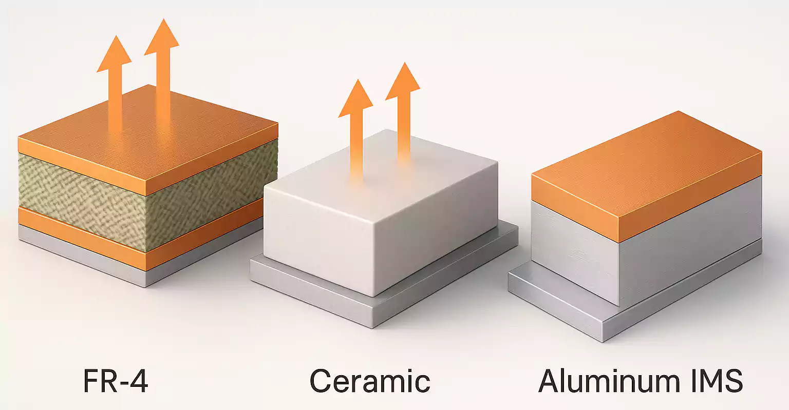
Ceramic PCB (AlN / Al₂O₃)
Ceramic materials like aluminium nitride (AlN) and aluminium oxide (Al₂O₃) are used when thermal or electrical performance requirements exceed FR-4’s limits.
- Key features: High thermal conductivity (especially AlN), low dielectric loss, excellent dimensional stability.
- Advantages: Ideal for high-power, high-frequency circuits; can withstand extreme temperatures.
- Limitations: More expensive and harder to process than standard laminates.
- Applications: Power modules, RF front-ends, automotive lighting, and laser systems.
Ceramic boards often use direct copper bonding (DCB) or direct-plated copper (DPC) methods to attach copper directly to the ceramic surface, thereby reducing thermal resistance.
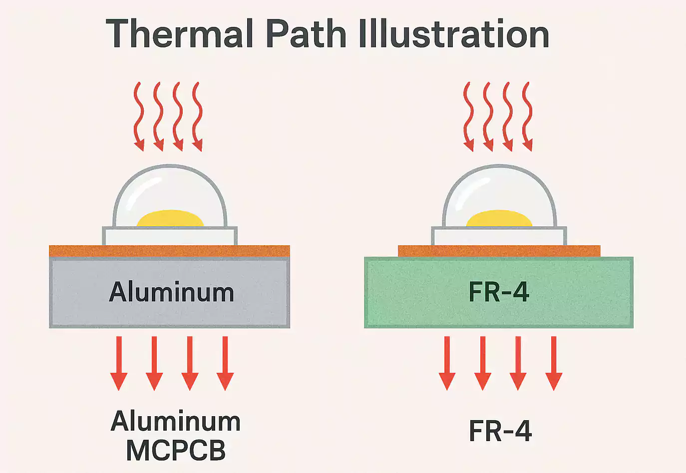
Aluminium-Based or Metal-Core PCB (IMS)
Metal-core PCBs use a thin dielectric layer bonded to a metal base (usually aluminium). This creates a direct thermal path from components to the metal layer.
- Structure: Copper foil + thin dielectric (0.1–0.3 mm) + aluminium base.
- Advantages: Excellent heat spreading and mechanical strength.
- Limitations: Usually limited to single or double layers; not suitable for complex multilayer or high-density interconnects.
- Applications: LED lighting, power supplies, motor drivers, and automotive electronics.
IMS boards are a cost-effective solution for designs that prioritise heat dissipation but don’t need multilayer routing.
Other Specialised Materials
- PTFE-based (Teflon) laminates – Used in RF, microwave, and millimetre-wave applications where ultra-low loss is required. They offer excellent high-frequency performance but are expensive and harder to process.
- Polyimide (PI) – Used in flexible and rigid-flex circuits; provides high thermal resistance and good mechanical flexibility.
Understanding Key Material Properties
| Tg (Glass Transition Temperature) | The temperature at which the resin changes from rigid to rubbery. High-Tg materials (>170 °C) handle high reflow temperatures and repeated thermal cycles. | Lead-free and automotive boards. |
| Dk (Dielectric Constant) | Determines signal propagation speed and impedance. Lower Dk materials reduce delay and signal loss. | High-speed or RF designs. |
| Df (Dissipation Factor) | Measures dielectric loss; lower Df means less signal attenuation. | High-frequency circuits. |
| CTE (Coefficient of Thermal Expansion) | How much a material expands with temperature. Matching CTE to copper and components reduces solder joint stress. | BGA and fine-pitch assemblies. |
| Thermal Conductivity | Indicates how well heat moves through the material. | Power and LED applications. |
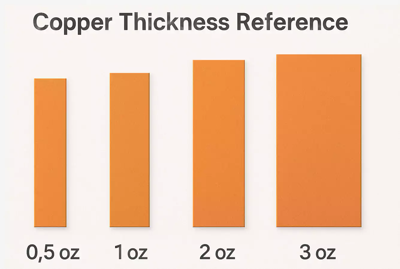
Copper Thickness and Application Mapping
Copper thickness affects current-carrying capacity, impedance, and heat dissipation.
- Conversion:
- 0.5 oz/ft² ≈ 17.5 µm
- 1 oz/ft² ≈ 35 µm
- 2 oz/ft² ≈ 70 µm
- 3 oz/ft² ≈ 105 µm
General rules:
- Signal and high-speed layers: 0.5–1 oz for better control and fine features.
- Power or ground layers: 1–2 oz for stable voltage and lower resistance.
- Heavy-copper boards (>3 oz): for high-current or power-handling applications.
Material Comparison Summary
| Thermal Conductivity | Low (~0.3 W/m·K) | Medium (20–30) | High (150–200) | Moderate (1–2 + metal base) |
| Dielectric Loss (Df) | Medium | Low | Very Low | Medium |
| CTE Match to Components | Moderate | Excellent | Excellent | Fair |
| Cost | Low | Medium | High | Low-Medium |
| Multilayer Capability | Excellent | Limited | Limited | Limited |
| Typical Applications | General electronics | RF, sensors | Power, RF, laser | LED, power supply |
Example Stack-Ups and Use Cases
- Multilayer FR-4: Common 4–8-layer boards using 0.5–1 oz copper, dielectric thickness adjusted for impedance control.
- Power or LED Modules (IMS): Single-layer structure with aluminium base for fast heat removal.
- High-Thermal Designs (Ceramic): AlN or Al₂O₃ substrates with direct copper bonding for high-power and high-frequency modules.
Each structure balances electrical performance, heat management, and cost.
Frequently Asked Questions
Q1: What are PCB boards made of?
PCBs are made of copper foil bonded to an insulating base such as FR-4, ceramic, or aluminium. They also include solder mask and silkscreen layers.
Q2: What’s the difference between a ceramic PCB and an aluminium PCB?
Ceramic PCBs (especially AlN) have higher thermal conductivity and lower loss, ideal for RF or power devices. Aluminium PCBs are cheaper and easier to produce, suitable for LED and power supply designs.
Q3: How do I choose copper thickness?
Use 0.5–1 oz for signal layers, 2 oz or more for power and heat-handling layers. Always consider trace width, via count, and total current flow.
Conclusion
Selecting the right PCB board material depends on three main factors: signal performance, heat management, and manufacturability.
- For general electronics, FR-4 remains the best all-around choice.
- For high-power or high-temperature designs, ceramic or aluminium-based PCBs deliver superior thermal performance.
- Always match material parameters like Tg, Dk/Df, CTE, and thermal conductivity to your application’s needs.
By understanding these core properties, you can design PCBs that are not only reliable but also optimised for performance, cost, and long-term durability.