


If you open any electronic device—from your phone to a power supply—you’ll find a printed circuit board (PCB) inside. It may look like a maze of green tracks and tiny parts, but every piece on that board has a specific role.
Understanding the parts of a PCB helps you read schematics, troubleshoot circuits, and design your own hardware with confidence.
Two Categories of PCB Parts
When people search for “parts of a PCB,” they often mean two different things:
- Electronic components – the resistors, capacitors, chips, and other devices mounted on the board.
- Board features – the copper layers, pads, vias, and markings that make up the board structure itself.
Let’s start with the components, then look at the physical features that bring them together.
Common Electronic Components and Their Functions
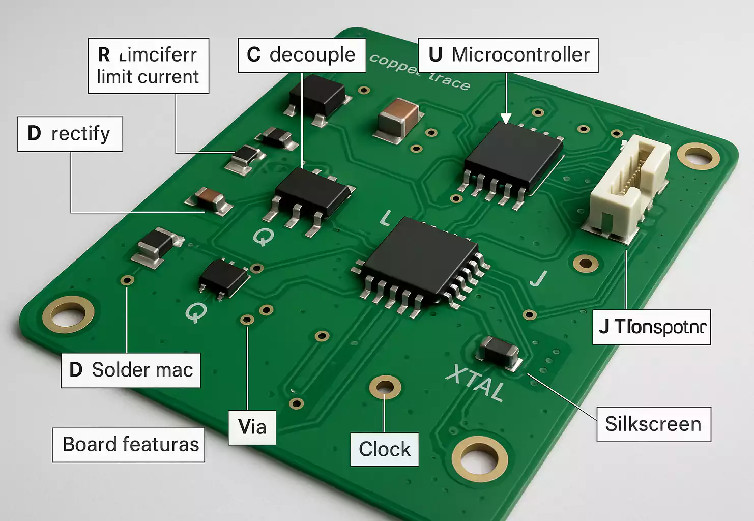
Each component on a PCB is labeled with a letter code called a designator.
These markings (R, C, L, D, Q, U, etc.) appear in the silkscreen layer and indicate the type of part.
Here are the most common components you’ll see on a modern PCB.
R – Resistor
Resistors limit or control the flow of electric current. They’re used for voltage division, biasing, and signal control.
They usually have a rectangular chip shape for SMT (like 0603 or 0402 sizes) or colored bands for through-hole types.
Resistors are non-polarized, so orientation doesn’t matter.
C – Capacitor
Capacitors store electrical energy and smooth voltage changes. They are essential for filtering and decoupling power rails.
Ceramic capacitors are tiny brown or beige chips with no polarity. Electrolytic and tantalum capacitors are polarized—look for a stripe or minus sign that marks the negative side.
L – Inductor
Inductors store energy in a magnetic field and are used in filters, converters, and EMI suppression.
They often appear as small coils or solid metal-cored blocks.
Inductors are also non-polarized.
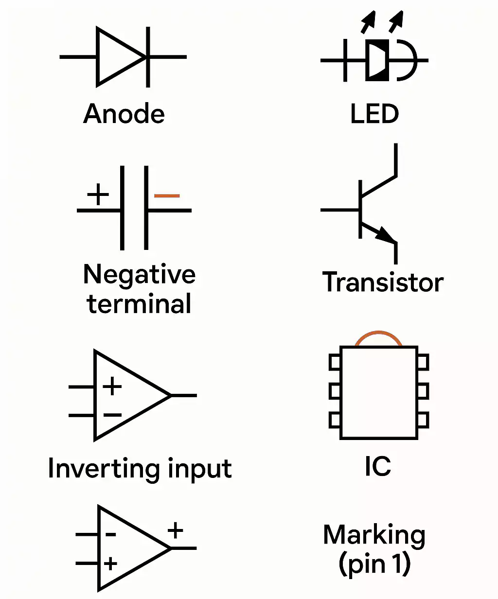
D – Diode / LED
Diodes let current flow in only one direction. They’re found in power protection and rectifier circuits.
Light-emitting diodes (LEDs) are special diodes that glow when current passes through.
Both types are polarized—the striped side is the cathode (negative).
Q – Transistor / MOSFET
Transistors act as electronic switches or amplifiers.
Small bipolar transistors (BJT) are labeled Q, while MOSFETs handle higher currents in power circuits.
Pay attention to pin order (base/gate, collector/drain, emitter/source) and heat-sink pads on larger parts.
U – Integrated Circuit (IC)
The “brains” of the PCB. ICs include microcontrollers, op-amps, drivers, logic gates, and more.
They come in many packages—SOIC, QFN, BGA—and are usually marked with a notch or dot to indicate pin 1.
ICs require careful orientation and ESD protection during assembly.
Y or X – Crystal / Oscillator
These parts create precise clock signals for timing circuits.
A quartz crystal works with a pair of capacitors to stabilize frequency.
Oscillator modules combine everything into a single package. They have no polarity but should match the circuit’s load capacitance.
F – Fuse, TVS, or MOV
These protective components prevent overcurrent or surge damage.
A fuse opens when current exceeds its rating.
TVS (transient voltage suppressor) diodes and MOVs protect against voltage spikes on power or communication lines.
SW or K – Switch / Relay
Switches manually open or close circuits.
Relays do the same using an electromagnetic coil for isolation.
You’ll find push buttons, slide switches, and relay blocks on control or power PCBs.
J or CON – Connector
Connectors link the PCB to other boards, cables, or external devices.
They come in many forms: headers, sockets, USB, HDMI, RF, and power jacks.
Connector orientation is critical; the key or notch ensures correct mating.
SEN – Sensor
Sensors convert real-world signals—such as temperature, light, pressure, and motion—into electrical signals.
They often connect to a microcontroller through analog or digital pins.
BAT – Battery Holder
Provides backup or main power to circuits such as real-time clocks.
Battery holders are polarized: the plus sign or larger pad marks the positive side.
Board Features: The Physical Parts of a PCB
Besides components, every printed circuit board has built-in features that connect and support them.
Copper Layers
The copper layers form the electrical traces and planes.
Outer layers carry visible tracks; inner layers may handle power or ground distribution.
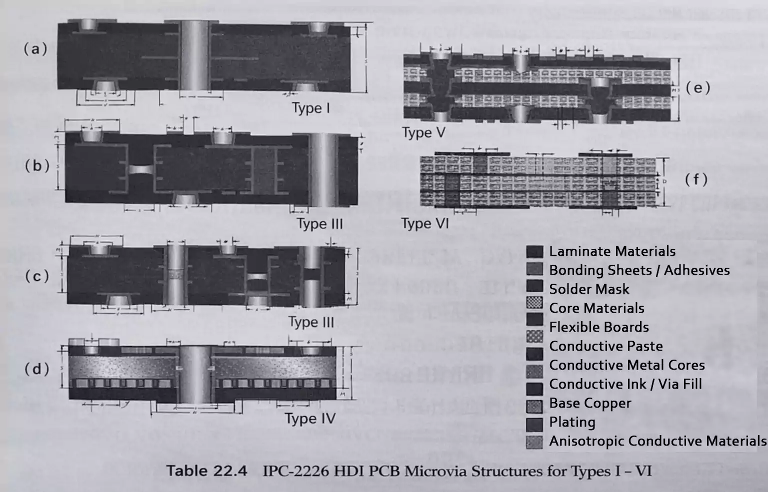
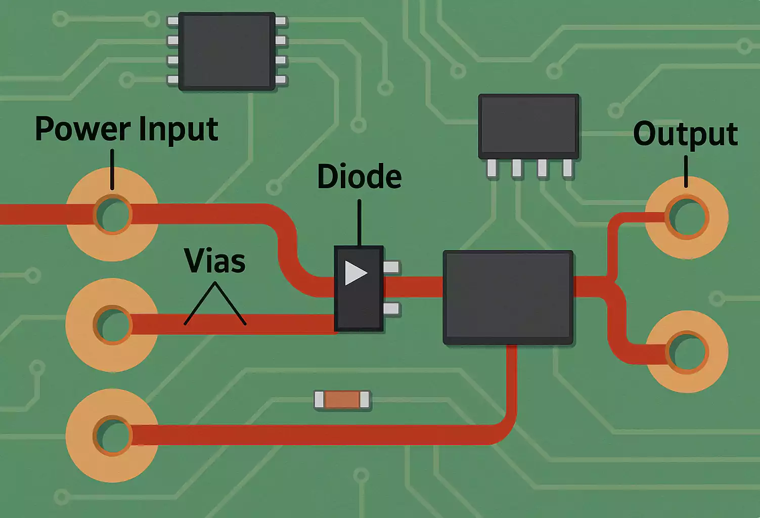
Pads and Vias
Pads are metal areas on the board where components are soldered.
Vias are small plated holes that connect signals between layers.
Through-holes (PTHs) are large enough for component leads; microvias and blind vias are smaller and connect only specific layers.
Solder Mask
The green (sometimes red, blue, or black) coating that covers copper areas.
It prevents solder bridges and corrosion.
Openings in the mask expose pads for soldering.
Silkscreen
White printed text and symbols on top of the mask.
It shows designators, logos, and polarity marks to help identify parts during assembly.
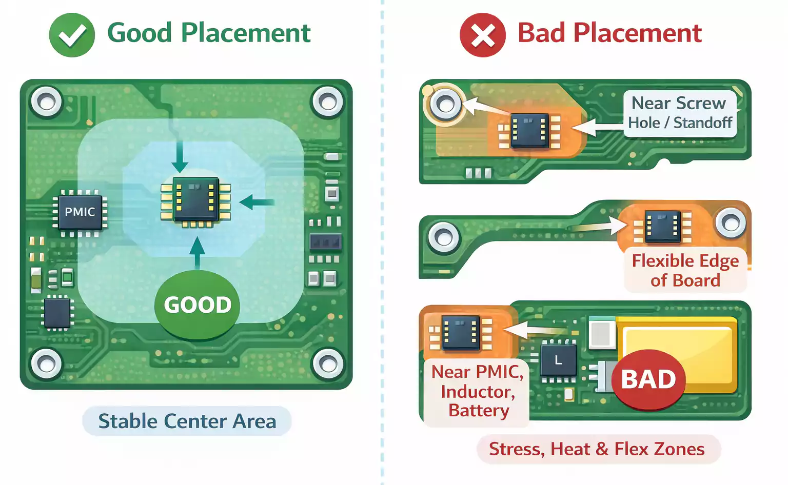
Test Points and Mounting Holes
Test points (TPs) are exposed pads used to measure voltage or signals during testing.
Mounting holes secure the PCB to enclosures or standoffs.
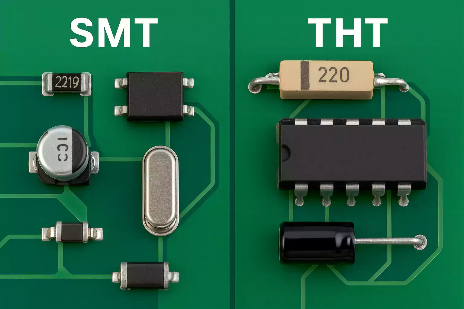
SMT vs. THT: How Components Are Mounted
There are two main ways components sit on a PCB:
- SMT (Surface-Mount Technology) – parts are soldered directly onto flat pads.
SMT allows smaller, lighter boards and is used for almost all modern electronics.
Solder paste is applied, parts are placed, and the board is placed in a reflow oven. - THT (Through-Hole Technology) – leads pass through holes and are soldered on the other side.
It’s common for large or high-power parts, such as connectors, transformers, and relays.
THT provides stronger mechanical support but takes more space.
Many boards today use a hybrid approach—SMT for most parts and THT for high-current or mechanical components.
Identification Tips and Common Mistakes
Knowing part symbols and polarity markings saves time and prevents damage.
Here are a few things beginners often get wrong.
- Polarity errors
- Electrolytic capacitors: the stripe marks the negative side.
- Diodes/LEDs: the banded end or flat edge is the cathode.
- ICs: pin 1 marked by a dot, notch, or bevel.
- Batteries: large pad or “+” silkscreen is positive.
- Mixing similar packages
Small resistors and capacitors (0402, 0603) look alike—always check labels before soldering.
Transistors in SOT-23 and SOT-223 packages are not interchangeable. - Wrong crystal load
Using the wrong capacitor values on a crystal can cause unstable or dead oscillation. - Mis-wired MOSFETs
Gate, drain, and source pins vary between packages. Always verify orientation with the datasheet. - Troubleshooting order
When something doesn’t work: - Inspect the silkscreen and polarity.
- Check continuity with a multimeter.
- Power the board only after verifying connections.
Following these steps helps prevent burnt parts and endless debugging sessions.
Typical Application Paths: Seeing the Circuit as a System
Once you can name each part, the next step is to understand how they work together.
Here are three common examples:
1. Power Supply Path
AC or DC input → Rectifier diodes (D) → Large electrolytic capacitor (C) →
Voltage regulator or DC-DC IC (U) → Inductor (L) → Output capacitor (C) →
Sampling resistor (R) and protection device (F or TVS).
This chain converts raw power into a stable DC voltage for the rest of the circuit.
2. Clock and Communication
Crystal (Y) + load capacitors (C) feed the microcontroller’s clock input.
At communication ports (USB, CAN, RS-485, Ethernet), you’ll often see ESD diodes, termination resistors, and common-mode chokes to protect and filter signals.
3. Sensing and Signal Conditioning
Sensors (SEN) produce small analog signals.
Those signals pass through resistor-capacitor filters, into an op-amp IC (U), and finally to an ADC inside the main controller.
Connectors (J) link the signals to external modules or measurement probes.
Thinking in terms of modules—power, timing, I/O—makes complex boards easier to understand.
FAQ: Quick Answers to Common Questions
Q1: Do “parts of a PCB” include the holes and markings, or just the components?
A PCB’s parts include both. Components perform electrical functions, while board features—like vias, pads, solder mask, and silkscreen—support and connect them.
Q2: How can I tell if a part has polarity?
Check the silkscreen or body markings. Anything that stores or directs current (capacitors, diodes, LEDs, ICs, batteries) usually has polarity. Passive parts like resistors and inductors do not.
Q3: What if I can’t read the silkscreen, or numbers are missing?
Look for the letter prefix (R, C, L, D, Q, U, etc.). Even without a full label, this tells you the part type.
Use a schematic or online part photo to confirm.
Q4: Why do some boards mix SMT and THT parts?
SMT saves space and cost, while THT provides strength for heavy or high-current components.
Mixing both gives the best balance of performance and durability.
Conclusion
A printed circuit board may look complex at first, but once you understand its main parts, it starts to make perfect sense. Every resistor, capacitor, and IC has a clear purpose, and the copper traces and layers simply connect them to make the circuit function as a single system.
Learning these basic PCB parts helps you recognize functions, check polarity, and troubleshoot problems quickly. With this knowledge, you can read boards more confidently and take the first step toward designing your own reliable circuits.
