Introduction
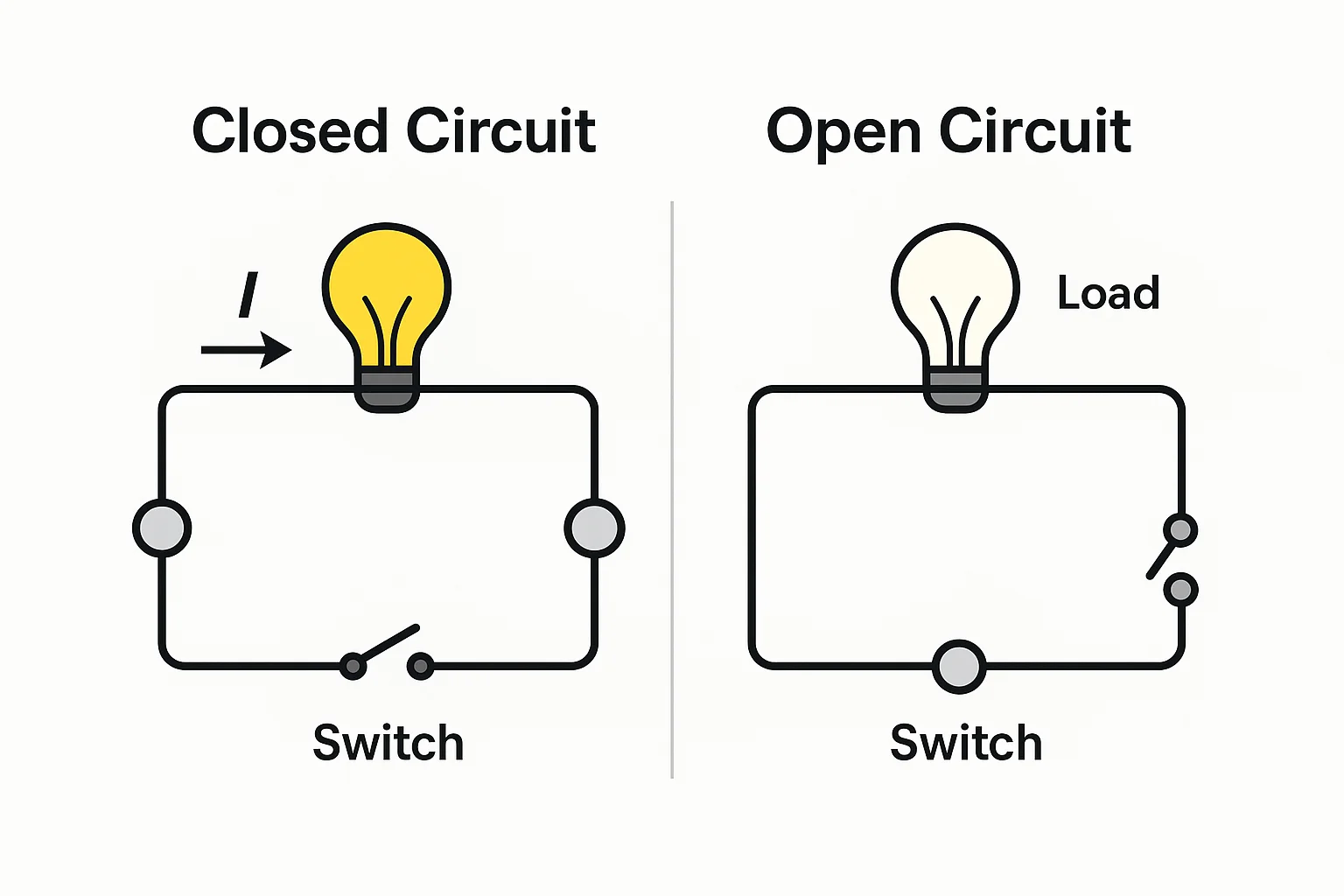
Imagine replacing a light bulb that refuses to illuminate, only to discover the filament is intact and full voltage is present at the socket. What gives? In most cases, the culprit is an open circuit—a break in the conductive path that stops current from completing its loop. Contrast that with a closed circuit, where electrons flow freely from the power source, through the load, and back again.
Grasping this distinction is more than textbook trivia; it underpins electrical safety, troubleshooting speed, and design reliability. Below are four concrete reasons every maker, technician, or engineer should master the concept:
1. Faster Diagnostics & Lower Downtime
Open-circuit symptoms—like voltage present with no current—demand different tests than short-circuit faults. Recognizing the tell-tale signs lets you reach the root cause quickly, whether it's a loose terminal, a blown fuse, or a damaged PCB trace.
2. Safer Maintenance Procedures
When a circuit appears "dead," verifying whether it's truly open or merely switched off upstream prevents accidental energization. Lock-out/tag-out protocols depend on confirming the circuit is open and isolated.
3. Smarter Component Selection
Designers routinely choose between normally-open (NO) and normally-closed (NC) contacts in relays, sensors, and emergency stops. Understanding open vs closed behavior ensures the device fails safe—crucial in life-safety and industrial automation systems.
4. Energy Efficiency & Cost Control
Unintended open circuits waste diagnostic hours; unintended closed circuits can waste power or create hazards. Differentiating the two helps optimize system uptime and energy usage alike.
By the end of this guide, you will be able to:
- Define open and closed circuits in plain language.
- Identify their electrical signatures using simple measurements.
- Apply best practices to real-world scenarios—from home wiring to industrial control panels.
Master these fundamentals now, and every future lesson in electronics—from Ohm's Law to advanced fault analysis—will click into place with far less friction.
Open vs Closed Circuit Comparison
Before we get lost in formulas and schematics, take 30 seconds to absorb the essentials. The table below condenses how an open circuit (often labeled OFF or no continuity) differs from a closed circuit (ON or complete loop) in the metrics that matter to technicians, students, and engineers alike.
| Criterion | Closed Circuit (Complete Loop) | Open Circuit (Broken Loop) | Practical Take-Away |
|---|---|---|---|
| Path Continuity | Every conductor forms an unbroken loop from source → load → source. | One or more breaks interrupt the loop. | Continuity is the defining attribute: design and diagnostics begin here. |
| Current Flow (I) | Non-zero; calculated by Ohm's Law ().I = V / R | ≈ 0 A; electrons can't complete the loop. | If your ammeter shows zero yet voltage is present, suspect an open. |
| Voltage Distribution | Most voltage drops across the load. | Source voltage often appears across the open gap. | Measuring full supply voltage on both switch terminals is a classic open-circuit clue. |
| Effective Resistance | Finite (depends on load). | Tends toward ∞ Ω between the open ends. | A continuity test that beeps or reads low Ω confirms closure; limitless Ω = open. |
| Power Delivered (P) | P = I × V (non-zero), load performs work. | ≈ 0 W; load is de-energised. | Explains why a bulb stays dark even when the socket shows full mains voltage. |
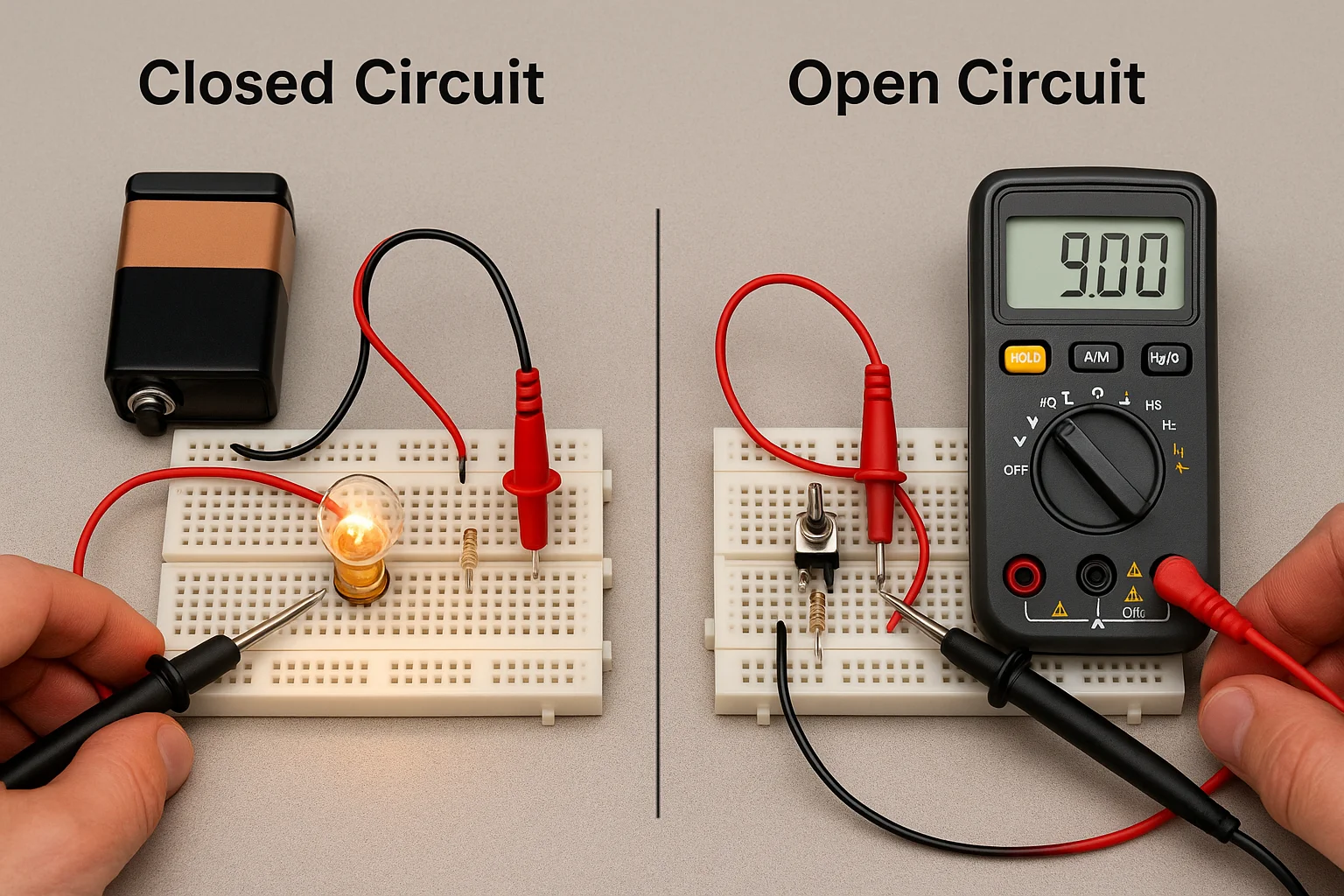
| Typical Examples | Light switch ON, motor running, phone charging. | Switch OFF, blown fuse, cracked solder joint, unplugged device. | Ground real-world visuals into the concept. |
| Safety Context | Conductors and load are live—shock risk. | Load is de-energised, but conductors upstream may still be live. | Always verify zero energy before servicing, even when the circuit "looks" open. |
| Schematic Symbol | Continuous line—switch drawn closed. | Intentional gap—switch drawn open. | Incorporate these icons in drawings for instant recognition. |
How to Use This Table in the Field
1. TroubleshootingIf you read the full supply voltage across two terminals but the device won't work, an open break is almost guaranteed. Start probing for loose wires, blown fuses, or corroded contacts.
2. Design & Safety
Choose normally-open (NO) or normally-closed (NC) contacts based on the desired fail-safe state. For example, emergency stops default to closed so any cable cut opens the control circuit and halts the machine.
3. Teaching & Learning
Pair the table with a hands-on demo: wire an LED in series with a switch, then measure current and voltage in each state. The live data cements the concepts shown here.
Foundation: Core Concepts Behind Open and Closed Circuits
A firm grasp of the basic building blocks makes every later section—fault-finding, design tips, and real-world case studies—far easier to digest. Below, we break down the four essential elements of any electric circuit, then zoom in on how those elements behave differently in closed and open states.
1. The Four Essential Elements of a Circuit
| Element | Role in a Closed Circuit | Role in an Open Circuit |
|---|---|---|
| Power Source (battery, PSU, alternator) | Provides continuous electromotive force (EMF) that drives current through the loop. | Still supplies voltage, but no current leaves the source because the loop is broken. |
| Conductors (wires, PCB traces) | Offer a low-resistance path for electrons to travel. | One or more conductors may be physically or electrically disconnected. |
| Load (lamp, motor, resistor, sensor) | Converts electrical energy into light, heat, motion, or data. | Receives no usable power; appears “dead” even if you measure full supply voltage across its terminals. |
| Control Element (switch, relay, fuse, breaker) | In the closed position, it completes the circuit; current flows. | When open, intentionally or due to failure, it interrupts the circuit. |
2. Closed Circuit in Detail
A closed circuit exists when all four elements connect seamlessly, allowing electrons to start at the negative terminal of the power source, traverse the conductors and load, and return to the positive terminal.
Key Characteristics
- Measurable Current Flow – A multimeter in the current mode shows a non-zero reading consistent with Ohm’s Law.
- Voltage Drop Across the Load – The bulk of the supply voltage appears across the load, not across switches or wires.
- Power Consumption – Calculated as, confirming the load is actively doing work (lighting, rotating, heating, etc.).
P = V × I - Practical Example – A phone charger plugged in and switched on: USB cable, charging IC, and phone battery create a closed loop, letting current replenish the battery.
Why This Matters
- Troubleshooting Benchmark – Establishing what "normal" looks like (current present, voltage drop across the load) sets a baseline for identifying abnormal open conditions later.
- Design Assurance – Confirming closed-loop integrity prevents intermittent faults, especially in high-vibration or high-temperature environments where connectors loosen or solder joints crack.
3. Open Circuit in Detail
An open circuit occurs when any part of that loop is interrupted. The break may be intentional—flipping a light switch—or accidental, like a corroded battery terminal.
Typical Causes
| Cause | Field Symptom | Quick Test |
|---|---|---|
| Manual Switch OFF | Device de-energised; full supply voltage present across switch terminals. | Measure continuity across switch; open reads infinite resistance. |
| Blown Fuse or Tripped Breaker | Zero current, but voltage often visible on one side of the fuse. | Inspect fuse element or breaker handle; replace/reset. |
| Broken Wire / PCB Trace | Intermittent or permanent loss of function, especially during movement. | Wiggle test or visual inspection under magnification. |
| Loose Connector / Terminal | Works sporadically; arcs or heat marks on contacts. | Reseat connector, tighten screw terminal, test continuity. |
Electrical Signatures
- Zero (or Micro-amp) Current – Even though you might read 5 V, 12 V, or 230 V across the circuit, the ammeter shows nearly 0 A.
- Full Source Voltage Across the Break – Because current cannot flow, no voltage is dropped elsewhere; the entire EMF appears across the gap.
- Infinite Resistance – A continuity test displays "OL" (over-limit) or megohms of resistance.
Impact on Safety & Reliability
- False Sense of Security – A device appears OFF, yet upstream wiring remains live; accidental contact can still cause electric shock.
- Troubleshooting Time Sink – Misidentifying an open as a faulty component leads to unnecessary part swaps and wasted labor.
- Preventive Maintenance Priority – Regular inspection of connectors, fuses, and cable routing minimizes unexpected opens in mission-critical systems.
Bottom Line
Mastering the interplay between these four circuit elements—and knowing how they differ in closed and open states—sets you up to diagnose faults faster, design safer products, and pass any electronics exam with confidence.
In the next section, we'll quantify those differences with formulas and real-world calculations so you can translate theory into actionable numbers.
Electrical-Level Deep Dive: Quantifying the Differences
While an at-a-glance table is great for quick reference, serious troubleshooting and design decisions require hard numbers. This section translates the qualitative differences between open and closed circuits into equations, sample calculations, and practical rules of thumb you can use in the lab or on the factory floor.
1. Current (I) — The Circuit's Lifeblood
| State | Governing Law | Expected Reading | Field Insight |
|---|---|---|---|
| Closed | Ohm's Law I = V / R_total | Non-zero (mA → kA, load-dependent) | Size fuses and conductors for this value + headroom. |
| Open | Loop incomplete → I ≈ 0 A | Multimeter shows 0 A (or μA if using a high-impedance meter) | Zero current despite full voltage is the hallmark of an open. |
Example:
A 24 V supply feeds a 120 Ω relay coil.
- Closed: → relay energises.
I = 24 V / 120 Ω = 0.20 A (200 mA) - Open: switch disconnects one lead → , relay drops out.
I ≈ 0 A
2. Voltage Distribution — Where Does the EMF Drop?
Closed Circuit: Voltage drops mainly across the load.
Relay example: 24 V across coil, near-zero across conductors and closed switch.
Open Circuit: Almost the entire source voltage appears across the break.
Pro-Tip: When your meter shows full supply voltage on both sides of a lamp holder yet the lamp is dark, suspect an open neutral or broken filament rather than a supply issue.
3. Resistance & Impedance — DC and Beyond
- DC Closed Loop: .
R_total = R_load + R_wiring - DC Open Loop: Effective resistance trends toward ∞ Ω between the open ends.
- AC Perspective: In closed AC circuits, add impedance () of inductors/capacitors. An open still pushes, forcing current to zero regardless of frequency.
ZZ → ∞
4. Power & Energy Transfer
| Formula | Closed Circuit | Open Circuit |
|---|---|---|
PowerP = V × I | Non-zero, equals energy converted by the load. | Approaches 0 W (no current). |
EnergyE = P × t | Accumulates over time; think battery discharge, motor work. | Essentially 0 J delivered to load. |
Quick Calc:
An LED strip draws 1 A at 12 V.
- Closed: ; running for 2 h → .
P = 12 WE = 24 Wh - Open: switch off → ; energy use stalls instantly.
P ≈ 0 W
5. Kirchhoff's Laws in Open vs Closed Context
Kirchhoff's Current Law (KCL)
Closed: Sum of currents entering a node equals sum leaving; current has somewhere to go.
Open: One path’s current is zero, so branch equations collapse—useful for diagnosing which leg is broken.
Kirchhoff's Voltage Law (KVL)
Closed: Algebraic sum of voltage drops in a loop equals the source EMF.
Open: Loop is incomplete; KVL cannot be applied until continuity is restored. Seeing full supply voltage across the gap is KVL's red flag that the loop is broken.
6. Diagnostic Cheat-Sheet
| Symptom | Likely Cause | Recommended Test |
|---|---|---|
| Full source voltage present across a device that won't operate | Open circuit upstream or inside the device | Continuity test on conductors and internal paths |
| Zero voltage across load, breaker not tripped | Breaker or switch open on live conductor | Probe continuity across control elements |
| Voltage oscillates when cables move | Intermittent open in flexing wire or connector | Wiggle test; inspect under load with oscilloscope or data-logging DMM |
Takeaways You Can Act On
- Sizing Components: Always compute closed-loop current to choose fuses, wire gauges, and MOSFET R_DS(on).
- Safety First: Treat "dead" equipment as live until proven open on both conductors; lock-out/tag-out verifies isolation.
- Troubleshooting Workflow: Measure voltage → measure current → perform continuity test. This triad quickly segregates opens from shorts and load failures.
Armed with these quantitative insights, you can move beyond "does it work?" to why it works—or fails. Next, we'll apply these principles to real-world scenarios, from household light switches to industrial crushing circuits, so you can practice spotting open and closed conditions in the wild.
Typical Applications & Scenario-Based Cases
Understanding open and closed circuits in the abstract is helpful; seeing them in real systems is priceless. Below are four high-impact settings—from household wiring to heavy industry—where the distinction guides troubleshooting, design, and safety.
1. Home & DIY Electrical
| Situation | Circuit State | Common Symptoms | Quick Fix / Best Practice |
|---|---|---|---|
| Wall switch controlling a ceiling light | Open when switch is OFF, closed when ON | Light fails to turn on; full mains voltage shows across the open switch | Verify switch continuity; upgrade to a rated dimmer if load is LED-based |
| Blown cartridge fuse in a distribution board | Open; fuse element has melted | Downstream outlets dead; upstream still live | Replace with same Amperage/time-delay rating; investigate overload cause |
| Loose neutral in a junction box | Intermittent open | Flickering bulbs or appliances that work only at certain angles | Re-terminate wire with proper twist length and a WAGO or screw connector |
2. Electronics Repair (PCB Trace & Component Level)
Broken Trace Diagnosis
- Symptom: Device powers on intermittently or only when the board is flexed.
- Method: Use "beep" continuity mode; place probes at both ends of the suspect trace. No beep → open.
- Remedy: Bridge with a fine-gauge wire jumper or re-flow solder under a microscope.
Open SMD Resistor/Capacitor
- Current path is broken inside the part.
- Replace component; double-check footprint solderability to avoid repeat opens.
3. Industrial Extensions
Crushing & Grinding Circuits (Mining)
- Open-Circuit Grinding: Ore passes through mill once, sizing decided by downstream screens. Equipment operates continuously; energy consumption lower per ton, but fine particles may be re-circulated inefficiently.
- Closed-Circuit Grinding: A classifier returns oversized material for re-grind. This "closed loop" increases uniformity but raises energy use.
- Takeaway: Engineers tweak the degree of closure to balance throughput, product size, and power cost.
Cooling Tower Water Loops (HVAC)
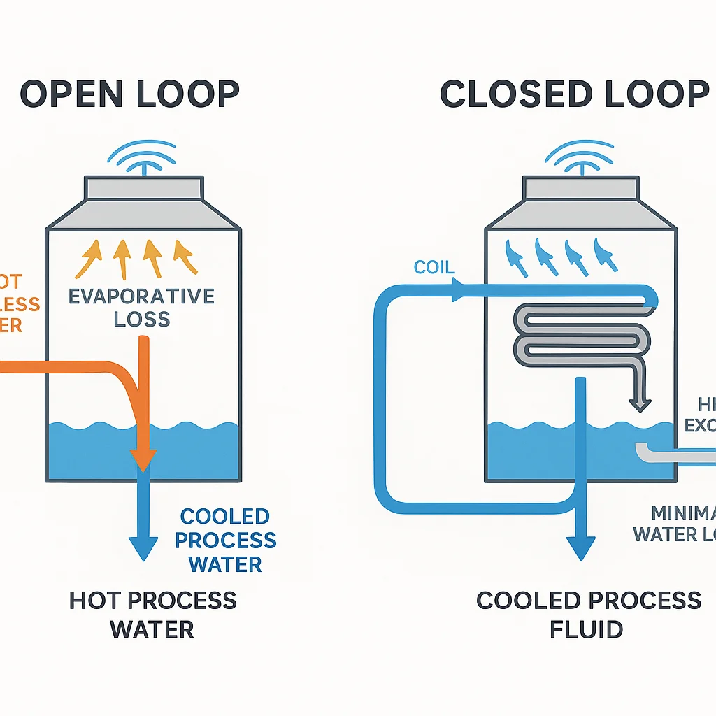
| Loop Type | Open Loop | Closed Loop |
|---|---|---|
| Water Exposure | Contacts ambient air; prone to scaling & biological growth | Sealed; uses a heat-exchange coil to isolate process fluid |
| Water Loss | Higher due to evaporation & drift | Minimal; only drift eliminator loss |
| Maintenance | Requires chemical dosing & periodic basin cleaning | Lower chemical load; coil cleaning schedule |
| Energy Efficiency | High latent heat removal; fan power optimized for wet-bulb temps | Slightly lower heat transfer; pumps work against extra coil resistance |
4. Safety Isolation vs Continuous Operation
When to Open a Circuit Intentionally
- Lock-out/tag-out before servicing machinery.
- Emergency-stop mushroom pushes: default to closed contacts in control logic so a broken wire forces the circuit open, halting motion.
When to Keep a Circuit Closed
Critical life-support equipment. Redundant power feeds ensure the circuit remains closed even if one path opens.
Data-center UPS systems: closed loops maintain zero-downtime power during utility switchover.
Rule of Thumb:
Design for fail-safe openness when human safety is paramount; design for fail-safe closure when uninterrupted service is critical yet safe on loss of power.
By mapping theory to these everyday and industrial contexts, you'll recognize open vs closed conditions at a glance, choose components wisely, and apply the right testing method without second-guessing—key skills that boost both productivity and safety.
Troubleshooting & Design Best Practices
Getting a stubborn circuit back online—or preventing it from failing in the first place—comes down to disciplined troubleshooting and rock-solid design. Use the five-step workflow below to clear open-circuit faults quickly, then apply the reliability tips that follow to keep closed circuits humming for years.
1. Five-Step Workflow for Open-Circuit Troubleshooting
| Step | Action | Tool / Meter Setting | Success Indicator |
|---|---|---|---|
| 1. Visual Survey | Scan for burnt traces, loose terminals, melted fuses, frayed insulation. | Eyes + flashlight | Defect spotted without powering the circuit. |
| 2. Voltage Check | Measure across suspected break points. | DMM on V mode | Full source voltage across two points = open path between them. |
| 3. Continuity Test | Isolate power; probe wire, switch, or fuse. | DMM "beep" (Ω) mode | Steady tone/low Ω confirms continuity; "OL" signals open. |
| 4. Wiggle / Stress Test | Flex harnesses or tap PCB lightly. | Same DMM setup | Reading flickers → intermittent open; trace movement reveals break. |
| 5. Component Isolation | Substitute or bypass suspect part (e.g., jumper a fuse holder). | Spare fuse, clip leads | Circuit energises → replaced part was open; no change → keep hunting. |
Pro Tip for Speed: Print this table, laminate it, and tape it to your workbench. Consistency beats guesswork and improves Mean Time To Repair (MTTR).
2. Design Tips for a Rock-Solid Closed Circuit
Choose the Right Contact Logic (NO vs NC)
- Life-safety controls: Use normally-closed wiring so any broken conductor forces the circuit open and stops the machine.
- Energy-critical loads: Use normally-open contacts to prevent accidental energisation when wiring fails.
Lock-In Connections
- Specify lever-actuated WAGO or locking Molex connectors.
- Add strain-relief clamps and grommets where cables bend or exit enclosures.
Protect Against Environment
- Conformal-coat PCBs in high-humidity zones.
- Use IP-rated glands and silicone gaskets for dust or splash protection.
Provide Redundant Paths Where Downtime Is Costly
- Dual feeder cables for telecom UPS systems.
- Ring or mesh topologies in industrial Ethernet.
Integrate Overcurrent & Thermal Safeguards
- Size fuses/breakers at 125% of steady-state current.
- Add thermistors or resettable PTCs near motors and transformers.
Embed Predictive-Maintenance Sensors
- Continuity-monitoring relays alert PLCs when resistance rises.
- Vibration or temperature sensors flag conditions that precede open faults.
Label, Document, and Train
- Laser-etch wire numbers; maintain up-to-date schematics in a cloud vault.
- Conduct annual "open-circuit drills" so technicians follow the five-step workflow instinctively.
Action Checklist
- During Build: Perform a 100% continuity sweep before first energisation.
- During Operation: Log voltage + current once per shift; deviations hint at growing opens.
- During Shutdowns: Inspect connectors, fuses, and cable routes; replace stressed parts proactively.
FAQs
What is the main difference between an open circuit and a short circuit?
An open circuit has an infinite or very high resistance that blocks current flow, while a short circuit offers near-zero resistance, causing an uncontrolled surge of current. Both prevent the load from working, but a short circuit poses a far higher fire and shock risk.
Why do I measure full voltage in an open circuit even though nothing works?
Because the loop is broken, no current flows and therefore no voltage drops across the load. Your meter—being high-impedance—reads the entire source voltage across the open gap.
Does the open-versus-closed concept apply to AC circuits?
Yes. Whether the supply is AC or DC, current needs a complete path. In AC, an open conductor still drives circuit impedance toward infinity, forcing current to zero.
How can I quickly test if a circuit is open?
1. Power off the circuit.
2. Set your multimeter to continuity (Ω) mode.
3. Probe both ends of the suspect path.
(1) Beep / low resistance → closed.
(2) “OL” / mega-ohms → open.
What's the safest way to service a circuit that appears open?
Treat every conductor as live until proven de-energised on both lines. Lock-out/tag-out the supply, verify zero voltage, and only then begin work.
Can a device fail "open" internally?
Absolutely. Components like fuses, resistors, capacitors, relay coils, and PCB traces often fail open, leaving the upstream voltage intact but starving the load of current.
When should I design with normally-closed (NC) contacts instead of normally-open (NO)?
Use NC (closed-when-idle) for fail-safe functions—e-stop buttons, safety guards, and fire-alarm loops—where any broken wire must trip the system to a safe state.
Why does a flickering light often point to an intermittent open circuit?
Small gaps or loose neutrals create a momentary open each time the conductor vibrates or heats. Current stops and restarts rapidly, causing visible flicker and eventual contact damage (arcing).
Conclusion & Key Take-Away Recap
Electrical troubleshooting often feels like hunting gremlins, yet 80% of "mystery" faults reduce to a single question: Is the circuit open or closed? Master that distinction and every other diagnostic step—voltage checks, continuity tests, component swaps—falls neatly into place.
One-Sentence Memory Hook
"If the path is complete, electrons compete; if the path is broken, electrons are token."(Translation: a closed loop lets real current flow, an open loop only shows voltage.)
Rapid-Fire Recap
| Pillar | What to Remember | Why It Matters |
|---|---|---|
| Definition | Closed circuit = continuous loop, current flows. Open circuit = break in loop, current ≈ 0 A. | Sets the diagnostic baseline. |
| Electrical Signatures | Closed: I ≠ 0, V drops on load. Open: I ≈ 0, full V across the break. | Prevents misreading "ghost voltage." |
| Troubleshooting Flow | Visual → Voltage → Continuity → Wiggle → Substitute. | Cuts MTTR by giving you a repeatable script. |
| Design for Reliability | Secure connectors, choose fail-safe NO/NC logic, add redundancy where downtime hurts. | Stops opens before they start. |
| Safety First | Verify open status on both conductors, lock-out/tag-out, size fuses at 125% load. | Keeps you shock-free and compliant. |
Resources
Circuit Troubleshooting Techniques: A Practical Guide - This post that blends hands-on multimeter tips with modern PSpice simulation workflows—ideal if you design or debug PCBs and want both hardware and software angles.
Troubleshooting Open and Shorted Series Circuits - Veteran instructor Tim Feiegenbaum walks through measurement strategy, tool selection, and common pitfalls in a concise video format—perfect for visual learners.
Troubleshooting an Open-Circuit Fault in the Control Circuit - Step-by-step industrial procedure focused on control transformers, contactors, and panel work—valuable for electricians and automation techs.
Fault Diagnosis of Analog Circuit Based on Spatial–Temporal Feature Attention Network - Uses deep-learning (CNN-BiLSTM) models to detect open-circuit and intermittent faults on complex PCBs with >97 % accuracy.