What Is an Open Circuit? (Definition & Principles)
An open circuit is an electrical circuit in which the current path is broken, preventing electricity from flowing. Even if a voltage source is connected, no current will flow unless the circuit is closed, meaning all connections are complete and continuous.
Open Circuit Definition (Simple Terms)
An open circuit occurs when one or more components in a circuit are disconnected, resulting in zero current flow despite the presence of voltage.
Open Circuit vs Closed Circuit: What's the Difference?
To understand open circuits more clearly, let's compare them with closed circuits:
| Feature | Open Circuit | Closed Circuit |
|---|---|---|
| Circuit Continuity | Broken / Interrupted | Complete / Connected |
| Current Flow | 🚫 No current | ✅ Current flows continuously |
| Example | Light switch in OFF position | Light switch in ON position |
| Resistance | Approaches infinity | Limited by the components inside circuit |
| Voltage Reading | May show voltage across open terminals | Voltage drop occurs across components |
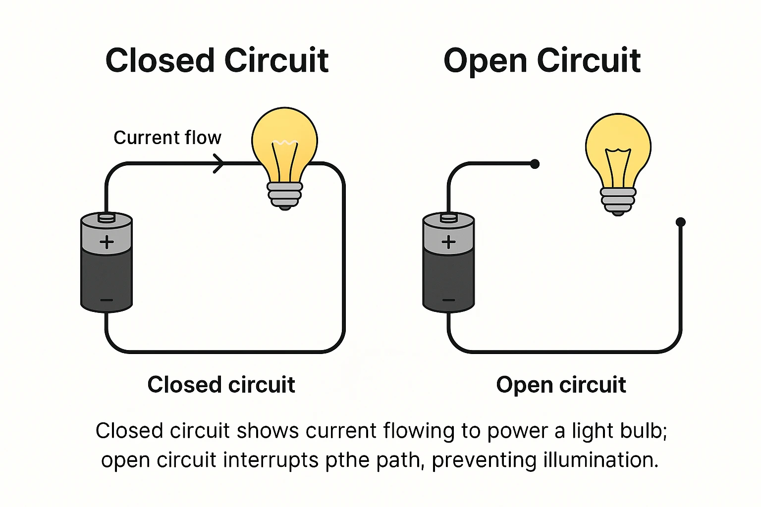
Example: Simple Battery and Light Bulb Circuit
Imagine a circuit where a battery is connected to a light bulb:
- In a closed circuit, the wire connects the battery to the bulb and back again, forming a loop. The bulb lights up.
- In an open circuit, if any part of the wire is missing or the switch is OFF, the loop is broken—no current flows, and the bulb remains dark.
Can Voltage Exist in an Open Circuit?
Yes. Voltage can still be present across the open points in the circuit, but without a complete path, there’s no current. This is why your multimeter might show voltage in an open circuit, even though nothing works.
An open circuit is like a bridge with a missing section—voltage is present, but current has nowhere to go. Understanding this basic concept is essential for troubleshooting electrical problems and designing reliable systems.
What Happens in an Open Circuit? (Current, Voltage, Resistance)
Understanding what occurs inside an open circuit is key to grasping how electricity works—and how to identify or troubleshoot electrical problems.
Even though a voltage source might be connected, the behavior of current, voltage, and resistance in an open circuit is quite different from that of a complete (closed) circuit.
Current in an Open Circuit: No Flow
In a closed circuit, electrons move in a continuous loop, allowing current to flow. But in an open circuit, that loop is broken—so current cannot move at all.
- Current (I) = 0 amps
- No matter how much voltage is applied, if the path is incomplete, the current will not flow.
- It's like a broken water pipe: even with pressure (voltage), no water (current) comes out.
Voltage in an Open Circuit: Can Still Exist
Surprisingly, voltage can still be present across the open terminals or break point in a circuit.
- Your multimeter may read full voltage across an open switch or disconnected wire.
- This is because potential difference still exists between two points, but there's no flow of charge.
Key Insight: Voltage is the potential to do work, but it only results in current if there's a closed path.
Resistance in an Open Circuit: Effectively Infinite
In a functioning circuit, resistance is determined by the materials and components the current flows through. In an open circuit, since current cannot flow:
- The effective resistance becomes extremely high or infinite
- No conductive path = no current = system behaves as if the resistance is unlimited
Real-World Impact
| Quantity | Open Circuit Behavior | Measurement Example |
|---|---|---|
| Current (I) | 0 A | Multimeter: "0" in ammeter mode |
| Voltage (V) | Present across open points | e.g. 9V across an open switch |
| Resistance (R) | Approaches infinity | Multimeter may show "OL" (over limit) |
In an open circuit, no current flows, voltage is present but unused, and resistance becomes infinite. Recognizing these conditions is essential for electrical troubleshooting and safety testing.
Real-World Examples of Open Circuits
Understanding open circuits conceptually is important, but seeing how they show up in everyday situations makes the concept more tangible.
Open circuits can occur intentionally (as part of a design) or unintentionally (as faults or failures). Below are real-world examples that demonstrate both.
1. Light Switch in the OFF Position
When you flip a wall switch to "OFF," it creates an intentional open circuit by breaking the connection between the power source and the bulb.
- Result: No current flows, so the light stays off
- Voltage may still be present on one side of the switch
2. Damaged Charging Cable
A frayed or broken wire in a phone or laptop charger often creates an accidental open circuit.
- Result: The device does not charge
- You may still measure voltage at the power adapter, but current doesn't reach the device
3. Faulty Brake Sensor in a Car
In automotive electronics, open circuits can occur when a sensor wire becomes disconnected or a solder joint cracks.
- Result: Warning lights activate, or safety systems fail
- Often intermittent—working only when the car isn’t vibrating
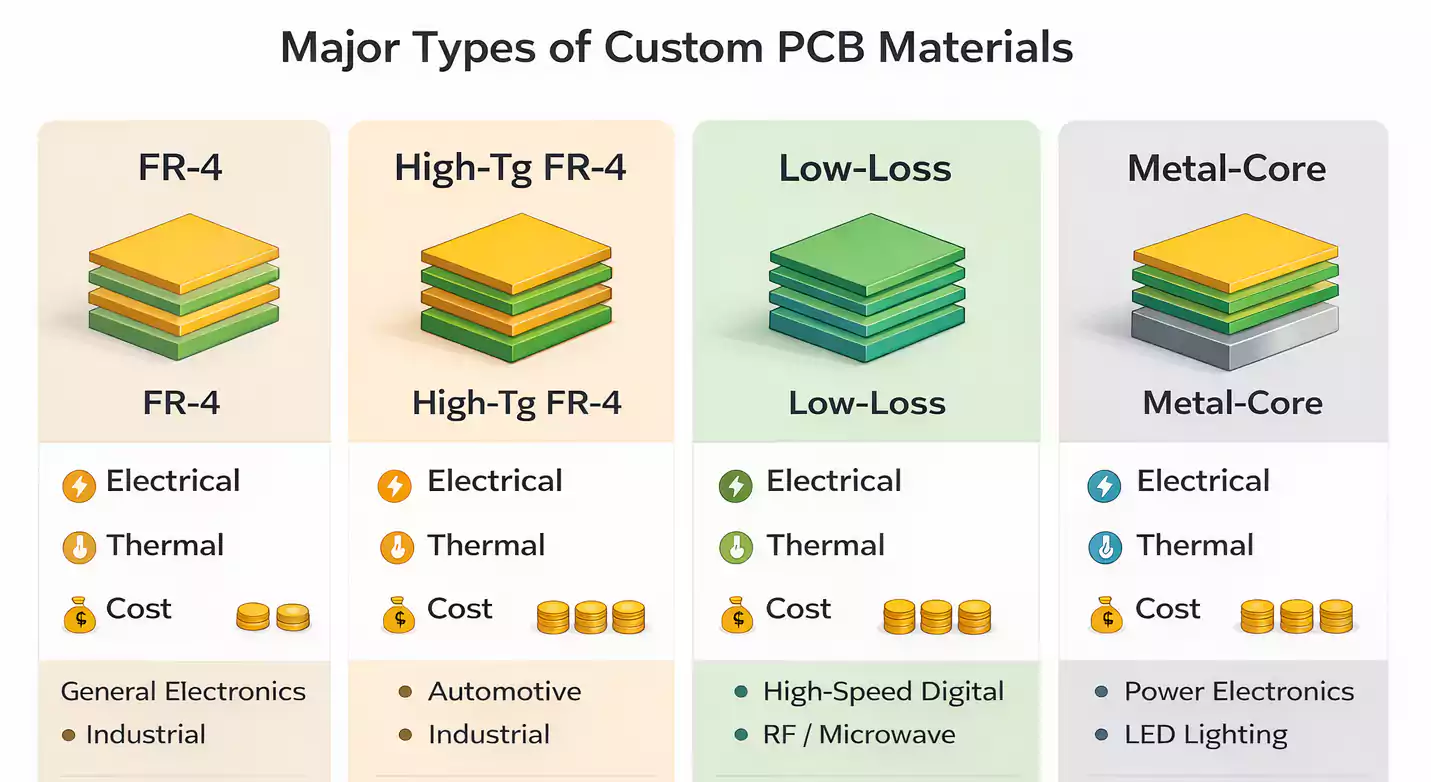
4. PCB Trace Crack in Electronics
On a printed circuit board (PCB), a hairline crack in a copper trace or an incomplete solder joint can cause an open circuit.
- Result: Device fails to power on or certain functions stop working
- Detected by: Continuity test, flying probe test, or X-ray inspection
5. Industrial Machine Malfunction
In factories, open circuits in control panels or relays may lead to sudden shutdowns or unexpected behavior in machinery.
- Result: Production stops or runs out of sync
- Often caused by: Loose terminal blocks or corroded contacts
6. Blown Fuse or Tripped Circuit Breaker
Fuses and breakers are designed to intentionally open a circuit in unsafe conditions.
- Result: Protects equipment and wiring from overheating
- Indicates: An overload or short circuit occurred previously
Open Circuit Examples at a Glance
| Scenario | Intentional or Fault? | Result |
|---|---|---|
| Light switch OFF | Intentional | No light (current stopped) |
| Broken phone cable | Fault | Device won’t charge |
| Automotive brake sensor failure | Fault | Error light / system fails |
| PCB solder crack | Fault | Device fails or acts intermittently |
| Blown fuse | Intentional | Power cutoff for safety |
| Loose terminal in machinery | Fault | Process stops or errors occur |
Open circuits are everywhere—from light switches to high-tech devices. Understanding where and why they occur helps users, engineers, and technicians detect, prevent, and solve electrical failures with confidence.
How Open Circuits Occur (Common Causes)
Open circuits can occur in a wide range of environments—from home electronics to industrial systems and PCBs. While some are intentional (like safety devices), most result from unexpected damage, wear, or design flaws.
Below are the most common causes of open circuits explained in practical, real-world terms.
1. Broken or Frayed Wires
One of the most frequent causes of open circuits is a physical break in the wire. Over time, wires can become brittle due to heat, flexing, or abrasion. In consumer electronics, this often happens with power cables, earphones, or charging cords. A single cut or fray can stop current flow completely, creating an open circuit.
2. Loose Connections or Terminals
Loose terminal screws, unplugged connectors, or oxidized contact points can interrupt electrical continuity. This is common in wall outlets, industrial panels, and relay systems. Even slight looseness can cause intermittent open circuits, leading to devices shutting down or malfunctioning unpredictably.
3. Cracked PCB Traces
On printed circuit boards (PCBs), fine copper traces carry current between components. If a PCB undergoes thermal stress, flexing, or poor handling, these traces can crack or delaminate, breaking the circuit path. Hairline fractures are difficult to see with the naked eye and often require continuity testing or inspection tools to detect.
4. Cold or Incomplete Solder Joints
In surface-mount and through-hole assemblies, poor soldering can result in "cold joints" connections that appear intact but fail to conduct electricity. This is a common open circuit cause in DIY electronics, mass production defects, or aging equipment. The result is often an unresponsive device or unstable performance.
5. Blown Fuses and Tripped Breakers
A fuse or circuit breaker is designed to create an intentional open circuit when current exceeds safe levels. This protective action stops current flow instantly to prevent fires or equipment damage. While not a fault, it is a deliberate open circuit condition that must be manually reset or repaired.
6. Corrosion and Oxidation
Electrical contacts exposed to moisture or chemicals may corrode over time. This oxidation increases resistance and can eventually form a complete break in continuity. Outdoor lighting, marine systems, and humid environments are especially vulnerable to this slow-forming open circuit cause.
Open circuits often result from mechanical damage, poor workmanship, or environmental stress. Whether you're troubleshooting a power failure or designing a circuit, knowing these common causes helps you prevent problems before they occur.
How to Detect an Open Circuit (Tools & Methods)
Detecting an open circuit is a vital step in electrical troubleshooting.
Whether you're repairing consumer electronics, automotive systems, or printed circuit boards (PCBs), knowing how to identify an open circuit quickly and accurately can save time, prevent downtime, and ensure safety.
Here are the most effective tools and methods used to detect open circuits—from simple DIY approaches to advanced industrial testing.
1. Using a Multimeter (Continuity or Resistance Mode)
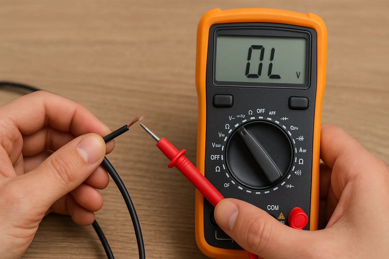
The multimeter is the most accessible and widely used tool for detecting open circuits. In continuity mode, it checks whether current can flow between two points.
- How it works: If the multimeter beeps or shows near-zero resistance, the circuit is continuous (closed). If there's no beep and the reading is "OL" (over limit), the circuit is open.
- Best for: Home appliances, cables, basic circuits, automotive wiring
- Pro tip: Always disconnect power before checking continuity to avoid damaging your meter.
2. Visual Inspection
In many cases, you can spot the cause of an open circuit with your eyes. Look for:
- Broken wires or traces
- Loose connections or unplugged components
- Burn marks or cracked solder joints
While it doesn't confirm conductivity, visual inspection is a fast way to identify obvious defects, especially on PCBs or wire harnesses.
3. Automated Optical Inspection (AOI)
AOI is used in PCB manufacturing to detect surface-level open defects caused by missing, misaligned, or poorly soldered components.
- How it works: High-resolution cameras scan the board and compare it to a "golden image"
- Finds: Missing components, cold solder joints, incorrect placements
- Used by: Electronics manufacturers for SMT quality control
4. Flying Probe Test (FPT)
A flying probe tester uses movable probes to contact test points and check electrical continuity across the PCB.
- Best for: Low-to medium-volume PCB testing, prototype validation
- Detects: Open traces, broken vias, misconnected nets
- Advantage: No need for a custom test fixture
5. In-Circuit Testing (ICT)
ICT is a high-speed method that uses a bed-of-nails fixture to apply voltage and measure current flow in each net.
- Used in: Mass production environments
- Detects: Opens, shorts, wrong components, missing parts
- Benefit: High coverage and automated data reporting
6. X-Ray Inspection
X-ray imaging is used to detect open circuits in hidden areas, such as under BGA components or inside multilayer PCBs.
- Reveals: Voids in solder joints, broken vias, internal cracks
- Ideal for: Complex boards, medical devices, aerospace electronics
- Limitation: Requires expertise to interpret images
Detecting an open circuit starts with simple continuity checks and scales up to advanced methods like X-ray and AOI. Choosing the right approach depends on your application, equipment, and the complexity of the system.
Open Circuit vs Short Circuit: Full Comparison
Understanding the differences between open and short circuits is essential for anyone working with electronics—whether you're a beginner or an engineer.
| Feature | Open Circuit | Short Circuit |
|---|---|---|
| Definition | Break in the path; current cannot flow | Unintended path with little/no resistance |
| Current Flow | ❌ No current | ⚠️ High, uncontrolled current |
| Resistance | Very high or infinite | Near zero |
| Voltage | Present across the open gap | Drops across the shorted connection |
| Risk Level | Typically low (device just doesn't work) | High (can cause overheating, fire, damage) |
| Common Causes | Broken wire, switch OFF, bad solder joint | Exposed wires, failed insulation, solder bridge |
| Detection Method | Multimeter shows "OL" or infinite ohms | Multimeter shows 0 ohms or continuity beep |
| Example Application | Light switch OFF, blown fuse | Wire pinched in appliance, PCB solder blob |
Which Is More Dangerous?
Short circuits are far more dangerous than open circuits. A short circuit can result in:
- Electrical fires
- Damaged electronics or batteries
- Shock hazards
That's why fuses and circuit breakers exist—to intentionally open a circuit when a short occurs and protect your system.
Applications Where Open Circuits Are Designed On Purpose
Not all open circuits are accidents or failures. In fact, open circuits are deliberately built into many electrical and electronic systems to serve specific safety, control, and functional purposes.
In these applications, temporarily interrupting the flow of current is exactly what the system needs to function correctly.
Here are some of the most common and important examples where intentional open circuits are used by design.
1. Switches (Manual or Automatic)
Every ON/OFF switch—whether it’s for a lamp, power tool, or computer—is based on the principle of creating an open circuit when turned off.
- How it works: Opening the switch breaks the circuit, stopping current flow
- Examples: Wall switches, push buttons, toggle switches, relay contacts
- Purpose: User control, energy savings, safety
2. Fuses and Circuit Breakers
Fuses and circuit breakers are safety devices that create intentional open circuits in case of electrical overloads or short circuits.
- Fuses melt when too much current flows, breaking the circuit
- Circuit breakers trip open and can be reset
- Purpose: Prevent fire, damage, or electric shock
3. Relays and Contactors (Normally Open Contacts)
In control systems, relays and contactors often include normally open (NO) contacts that start as open circuits.
- When activated, the relay closes the circuit to allow current flow
- When deactivated, the contact returns to its open state
- Used in: Automotive systems, HVAC, automation equipment
4. Emergency Stop Buttons (E-Stops)
Industrial machines and robotics use E-stop buttons that work by breaking the circuit when pressed—creating an immediate open circuit to stop all power flow.
- How it works: Cuts power to motors, actuators, or control boards
- Purpose: Ensure operator safety during emergencies
5. Thermal Switches and Temperature Sensors
Devices like thermal switches, thermistors, or PTC resettable fuses create an open circuit when a system overheats.
- Result: Interrupts current to protect the device from thermal damage
- Returns to normal: Some are self-resetting, others require replacement
- Used in: Battery packs, motors, appliances
Intentional open circuits are a vital part of electrical design for safety and control. From your home light switch to industrial emergency shutdowns, these open paths serve essential functions in modern systems.
Understanding where open circuits are purposeful—vs. where they signal a fault—helps you design smarter systems and troubleshoot with greater accuracy.
How to Prevent Unintentional Open Circuits
While some open circuits are intentional and essential to circuit design, unintentional open circuits can lead to system failures, downtime, or safety issues.
These unexpected breaks in the current path are often caused by poor design, environmental stress, or manufacturing defects.
Here are effective strategies to help prevent unintentional open circuits in everything from simple wiring to complex printed circuit boards (PCBs).
1. Use Quality Components and Materials
Open circuits often begin with cheap or poorly manufactured materials, especially in wiring and soldering.
- Choose high-quality connectors, wires, and solder materials
- Use proper wire gauges to avoid breakage
- Select reliable PCBs from certified fabricators (e.g., IPC-compliant)
2. Design for Durability and Flexibility
Mechanical stress, vibration, or thermal expansion can cause wires to fray or traces to crack.
- Add strain relief to cable ends and solder joints
- Avoid sharp bends in wire routing
- Design PCB traces with adequate width and clearance
- Use flexible PCBs for moving or compact parts
3. Ensure Proper Soldering Techniques
Cold or incomplete solder joints are a leading cause of open circuits in both manual and automated assemblies.
- Use the correct temperature profile in reflow soldering
- Apply flux to improve wetting and reduce oxidation
- Inspect solder joints visually or with AOI/X-ray if available
4. Perform In-Process Testing and Inspection
Catch open circuits before they reach the end-user with layered testing strategies:
- AOI to spot missing or defective joints
- Continuity testing with a multimeter for hand-soldered items
- Flying probe or ICT testing for PCBs
- Include functional tests at the final stage
5. Protect Against Environmental Factors
Corrosion, moisture, and dust can break electrical continuity over time.
- Use conformal coatings on PCBs in high-humidity environments
- Install sealed or waterproof connectors
- Apply dielectric grease to terminals in automotive or marine use
For industrial or mission-critical systems, build a schedule for:
- Regular visual inspections of wiring and contacts
- Thermal scanning to spot stressed components
- Vibration and stress tests for mobile systems
- Logging and alerts from smart sensors for early detection
Preventing unintentional open circuits is not just about fixing problems—it's about engineering them out of your system through better design, assembly, and inspection. These proactive steps not only enhance reliability but also reduce long-term costs and improve safety.
FAQs
What is an open circuit?
An open circuit is a break in the electrical path, which prevents current from flowing. Even if voltage is present, no electricity can flow until the circuit is closed or completed.
What causes an open circuit?
Common causes include broken wires, cracked PCB traces, cold solder joints, corroded terminals, or disconnected components. Environmental stress, poor manufacturing, and physical damage are often to blame.
Can voltage exist in an open circuit?
Yes. Voltage can still be measured across the open points in a circuit, but since there's no complete path for electrons to flow, there is no current.
How do I find an open circuit?
Use a multimeter in continuity or resistance mode. A reading of "OL" or infinite resistance indicates an open circuit. In manufacturing, tools like AOI, flying probe testers, and X-ray inspection are commonly used.
What's the difference between an open and a short circuit?
An open circuit has infinite resistance and no current, while a short circuit has almost no resistance and allows excessive current, which can lead to component damage or fire hazards.
Are open circuits dangerous?
Open circuits are usually not dangerous—they just stop the device from functioning. However, they can lead to safety risks in critical systems like medical devices, automotive sensors, or industrial controls.
Can open circuits happen over time?
Yes. Open circuits can develop over time due to corrosion, vibration, thermal cycling, or aging components, especially in harsh environments.
How do I prevent open circuits?
Use quality materials, ensure proper soldering, apply environmental protection, and design for mechanical durability. Regular testing and preventive maintenance also help catch problems early.
Conclusion
Open circuits may seem like a basic electrical concept, but their real-world impact is anything but simple. From stopping your phone from charging to triggering failures in mission-critical medical or automotive systems, open circuits are everywhere—sometimes by design, and often by mistake.
By understanding what an open circuit is, how it behaves, and where it commonly occurs, you're better equipped to diagnose, prevent, and engineer around this important electrical condition. Whether you’re a hobbyist, technician, or electronics manufacturer, mastering open circuits is a foundational skill for building safe and reliable systems.
Ready to Go Deeper? Work With Fast Turn PCB
If you're dealing with intermittent failures, production defects, or just want to ensure your next design is built for electrical continuity, we're here to help. With advanced testing capabilities, DFM expertise, and world-class PCB manufacturing, we help businesses eliminate open circuit risks—before they cause failure.