


Introduction
Choosing the right PCB material is crucial—especially for high-frequency applications where signal integrity, thermal stability, and dielectric performance matter. Two of the most commonly used materials are FR4 and Rogers laminates, each with distinct advantages.
FR4 is valued for its affordability and wide availability, making it ideal for general-purpose PCBs. In contrast, Rogers materials offer superior dielectric consistency and low signal loss, making them better suited for RF, microwave, and 5G designs.
This article offers a clear, engineer-focused comparison between FR4 and Rogers, covering critical aspects like dielectric constant (Dk), loss tangent, cost differences, and typical use cases. Whether you're designing a basic circuit or a high-speed RF board, this guide will help you choose the optimal material for your application.
Technical Comparison of FR4 vs Rogers PCB Materials
Selecting the right PCB material requires a solid understanding of the technical properties that affect signal integrity, thermal performance, and design reliability. Below is a technical comparison between FR4 and Rogers high-frequency laminates, focusing on the most critical factors in PCB design.
1. Material Composition & Structure
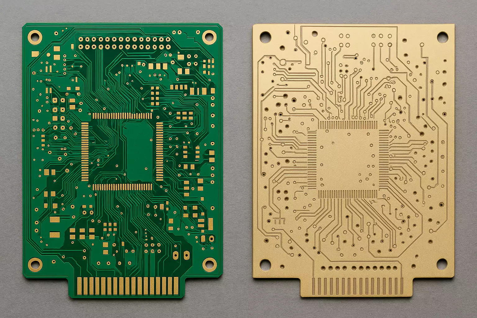
- FR4: A glass-reinforced epoxy laminate widely used in consumer and industrial electronics. It is inexpensive, easy to process, and mechanically stable, but its dielectric properties degrade at higher frequencies.
- Rogers: A family of advanced PCB materials based on hydrocarbon, ceramic-filled, or PTFE substrates, optimized for RF and microwave applications. Rogers laminates offer exceptional electrical consistency and low signal loss.
2. Core Property Comparison Table
| Property | FR4 | Rogers RO4003C | Relevance |
|---|---|---|---|
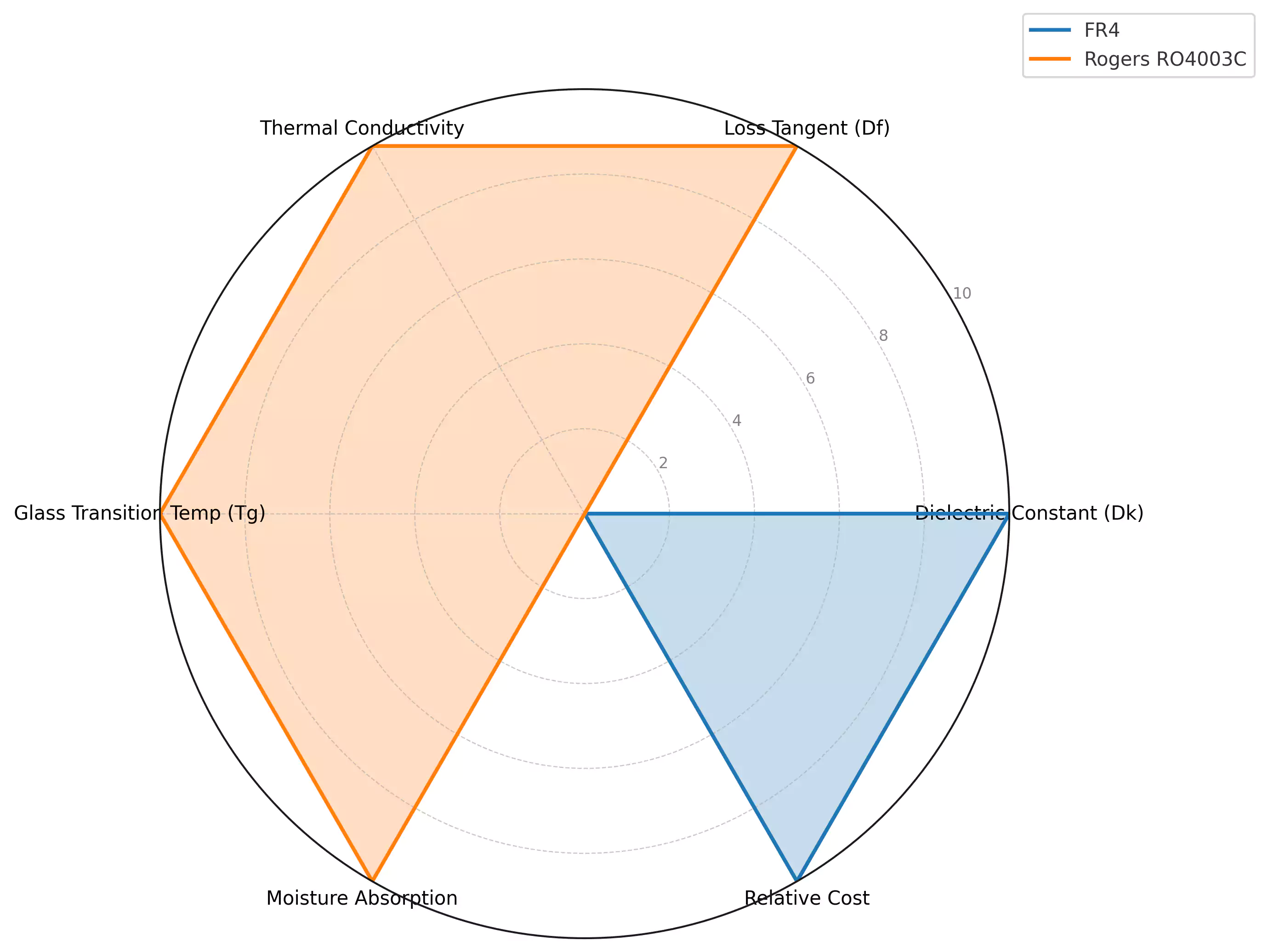
| Dielectric Constant (Dk) | ~4.4 (variable with temp/frequency) | 3.38 (stable up to 10+ GHz) | Affects signal speed and impedance control |
| Loss Tangent (Df) | 0.020–0.025 | 0.0027 | Determines signal loss, especially at RF |
| Thermal Conductivity | ~0.25 W/m·K | ~0.50 W/m·K | Impacts heat dissipation in dense designs |
| Glass Transition Temp (Tg) | ~135°C | >280°C | Influences thermal reliability during reflow |
| Moisture Absorption | 0.10% – 0.20% | ~0.06% | Lower is better for environmental stability |
| Frequency Range | Up to ~1 GHz | 500 MHz to 20+ GHz | Rogers supports high-speed & RF circuits |
| Impedance Stability | Moderate | Excellent | Crucial for signal integrity in high-speed PCBs |
| Process Compatibility | Industry standard | Requires more control | Rogers may need special drills/prep steps |
| Relative Material Cost | Very low | High | Cost is often the deciding factor |
3. Performance Implications for Design Engineers
Dielectric Constant (Dk)
- FR4: The Dk of FR4 tends to fluctuate with frequency and temperature, making it difficult to maintain impedance accuracy in high-speed or RF designs.
- Rogers: Offers stable and predictable Dk, which ensures consistent impedance and signal timing—essential for microwave, antenna, and 5G applications.
Loss Tangent (Df)
- The loss tangent directly influences how much signal energy is lost as heat.
- Rogers materials exhibit significantly lower loss, resulting in cleaner signals at higher frequencies and longer trace lengths without degradation.
Thermal and Environmental Stability
- Rogers laminates outperform FR4 in heat resistance, thermal cycling, and moisture protection. This is particularly beneficial in automotive, aerospace, and harsh environment applications.
Manufacturability
- FR4 is easier to source and process due to its widespread use.
- Rogers materials (especially PTFE-based) may require special tooling, drilling, and lamination techniques, though the RO4000 series is engineered to be compatible with standard FR4 processes.
Cost vs Performance Analysis: FR4 vs Rogers
When choosing between FR4 and Rogers PCB materials, cost is often the first factor that engineers and procurement teams consider. However, performance—especially in high-frequency environments—should not be underestimated.
1.Material and Fabrication Cost Comparison
| Cost Factor | FR4 | Rogers RO4003C / Similar | Notes |
|---|---|---|---|
| Raw Material Price | $0.10–$0.30/in² | $0.80–$1.50/in² | Rogers is 3–5x more expensive per unit area |
| PCB Manufacturing Cost | Standard | Higher due to material handling | Rogers may require controlled lamination, special drills |
| Tooling & Processing | Minimal | May require extra steps (PTFE prep, etc.) | RO4000 series is more FR4-compatible than PTFE Rogers |
| Yield Rate | High | Slightly lower (more sensitive to error) | Impacts cost in high-volume production |
| Turnaround Time (TAT) | Fast, readily available | Longer lead time | Rogers often requires special ordering or stocking |
2.Performance Value Comparison
| Performance Metric | FR4 | Rogers (e.g. RO4003C) | Impact on Application |
|---|---|---|---|
| Signal Loss @ High Frequency | High | Very Low | Rogers ensures integrity at GHz-range frequencies |
| Impedance Control | Less predictable | Highly stable | Crucial for RF lines, antennas, and differential pairs |
| Dielectric Consistency | Varies with temp/frequency | Stable across wide ranges | Enables repeatable performance in critical designs |
| Thermal Reliability | Moderate (Tg ~135°C) | High (Tg >280°C) | Withstands soldering and thermal cycling better |
| Moisture Resistance | Susceptible | Excellent | Improves long-term reliability in humid environments |
| Long-Term Performance | Degrades over time | Maintains specs over lifespan | Especially important for aerospace, automotive, telecom |
3.When to Choose FR4 or Rogers?
| Use Case | Recommended Material |
|---|---|
| Budget-driven consumer electronics | FR4 |
| Low-frequency analog or digital signals | FR4 |
| Wi-Fi, Bluetooth modules | Depends on frequency |
| High-speed digital (DDR, SerDes, etc.) | Rogers preferred |
| 5G antennas and RF front ends | Rogers |
| Satellite, radar, automotive radar | Rogers |
| Mixed stack-up designs | Hybrid (FR4 + Rogers) |
Detailed Breakdown of Rogers PCB Material Series
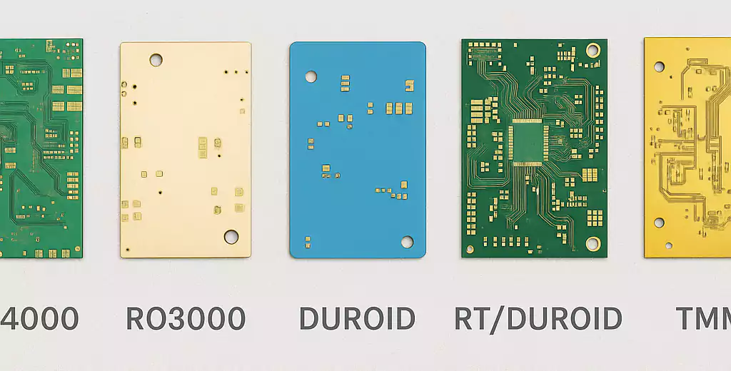
Rogers Corporation offers a diverse portfolio of high-frequency PCB laminates, each engineered for specific electrical performance, thermal requirements, and manufacturing compatibility. Unlike FR4, which is a general-purpose, single-category material, Rogers laminates are divided into specialized series—such as RO4000®, RO3000®, and Duroid®—designed to meet the demands of RF, microwave, and high-speed digital circuits.
Each Rogers material series features unique characteristics in terms of dielectric constant (Dk), loss tangent (Df), thermal stability, and frequency handling capabilities.
1. Overview Table: Key Rogers Material Series
| Rogers Series | Dielectric Constant (Dk) | Loss Tangent (Df) | Max Frequency | Key Features | Typical Applications |
|---|---|---|---|---|---|
| RO4000® | 3.38–3.55 | ~0.0027 | ~10–15 GHz | Cost-effective, FR4-compatible processing | RF modules, antennas, IoT, automotive radar |
| RO3000® | 3.0–10.2 | ~0.0013–0.002 | >20 GHz | Ceramic-filled PTFE for ultra-low loss | 5G mmWave, aerospace, satellite comms |
| Duroid® | 2.2–10.2 | ~0.0009–0.0025 | 20–77+ GHz | Ultra-stable, high-performance, military-grade | Radar, missiles, high-power RF/microwave |
| RT/duroid® 6000 | ~2.94 | ~0.0012 | >40 GHz | Designed for low Dk drift in harsh environments | Space, defense, phased-array antennas |
| TMM® | 3.27–12.85 | ~0.0018–0.0022 | ~30+ GHz | Thermoset ceramic polymer, dimensionally stable | Filters, power amplifiers, dielectric resonators |
2. RO4000® Series: Cost-Effective RF Performance
The RO4000 series (e.g., RO4003C, RO4350B) is the most widely used and considered the "gateway" into Rogers materials. These laminates are designed to deliver excellent electrical performance while remaining compatible with FR4 fabrication processes (e.g., standard epoxy prepreg, drill speeds).
- Dielectric Constant (Dk): ~3.38 (RO4003C)
- Loss Tangent: ~0.0027
- Benefits:①FR4-like processability、②Good for low-to-mid GHz RF circuits、③Lower cost than PTFE-based materials
- Ideal for: Wi-Fi, IoT, automotive radar (24 GHz), hybrid stack-ups with FR4
3. RO3000® Series: Advanced RF and mmWave Performance
The RO3000 series (e.g., RO3003, RO3035) are ceramic-filled PTFE laminates, designed for low-loss, high-frequency applications such as 5G mmWave and aerospace radar.
- Dielectric Constant (Dk): Range from 3.0 to 10.2
- Loss Tangent: As low as 0.0013
- Benefits:①Exceptional electrical stability across wide frequency/temperature ranges、②Minimal phase distortion、③Lower insertion loss at >20 GHz
- Ideal for: 5G antennas, phased-array systems, satellite communications
4. Duroid® Series: Ultimate High-Frequency Reliability
The Duroid® line (e.g., RT/duroid 5880, 6002, 6010.2) is engineered for mission-critical applications where minimal dielectric loss, extreme thermal stability, and high reliability are essential.
- Dielectric Constant (Dk): From 2.2 to over 10
- Loss Tangent: As low as 0.0009
- Features:①Very low moisture absorption、②Superior phase and impedance stability、③Suitable for extreme environments
- Ideal for: Aerospace, military radar, missiles, high-power RF amplifiers
5. Choosing the Right Rogers Material: Engineer’s Guide
| Design Priority | Recommended Series |
|---|---|
| Cost-effective RF performance | RO4000 (RO4003C) |
| mmWave 5G / low-loss high frequency | RO3000 (RO3003) |
| Harsh environment / radiation stable | RT/duroid 6000 |
| Wideband, high-power microwave | Duroid 5880 / 6010.2 |
| Compact RF filters / resonators | TMM® Series |
Practical Design Considerations When Using FR4 and Rogers Materials
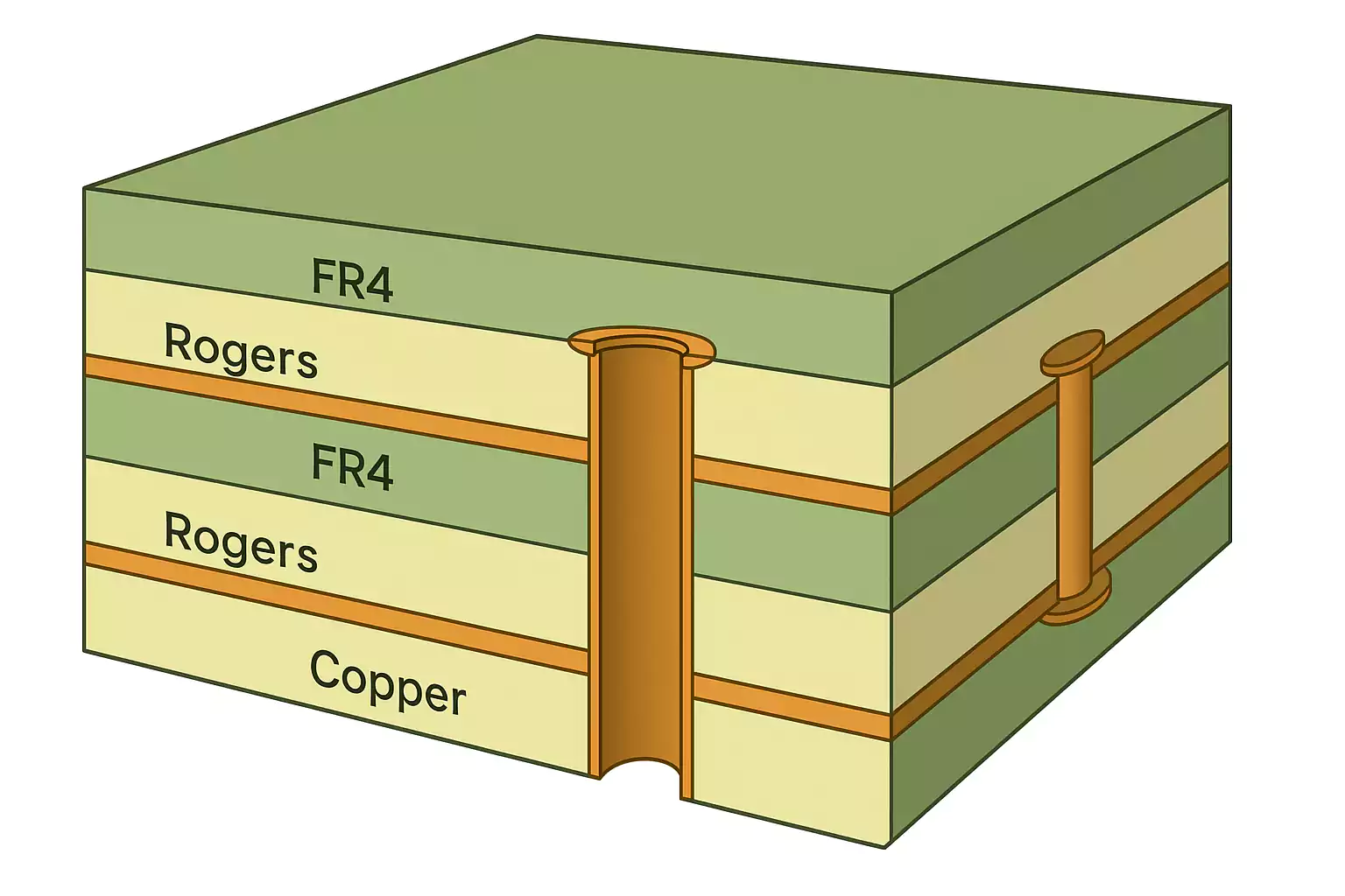
1. Hybrid Stackups: Mixing FR4 and Rogers
To balance performance and cost, many engineers use hybrid stackups—placing Rogers laminates only on high-speed signal layers, while using FR4 for ground or power planes. While effective, hybrid boards require careful control of layer bonding and CTE (coefficient of thermal expansion) differences to prevent delamination or warping during reflow.
2. Impedance Control and Signal Integrity
Rogers materials offer tighter impedance tolerance due to their stable dielectric constant. For high-speed traces or RF lines, this helps maintain consistent signal performance. In contrast, FR4’s varying Dk may lead to unpredictable impedance, which is especially problematic in microwave circuits and differential pairs.
3. Thermal Management
Rogers laminates typically feature higher glass transition temperatures (Tg) and better thermal conductivity, which improve performance in high-power or thermally stressed environments. If using FR4 in such designs, additional thermal vias, copper pours, or heatsinks may be required to manage heat dissipation.
4. Moisture Sensitivity
FR4 absorbs more moisture than Rogers, which can affect dielectric performance and reliability. In humid or outdoor environments, Rogers materials are preferable due to their low moisture absorption and stability, reducing the risk of dielectric drift and signal degradation over time.
5. Manufacturing Considerations
While FR4 is compatible with almost all PCB fabrication processes, some Rogers materials require special handling. For example, PTFE-based laminates may need plasma treatment, special drills, or controlled lamination temperatures. That said, RO4000 series laminates are designed to be FR4 process-compatible, easing the transition for most manufacturers.
6. Design for Manufacturability (DFM)
When designing with Rogers, always consult your PCB fabricator early. Share stackup drawings, material specs, and target impedance to ensure tooling, etching, and lamination processes are properly adjusted. Rogers boards may also need tighter etching tolerances to preserve trace width accuracy.
Application Scenarios and Material Recommendations
Consumer Electronics (Low-Frequency)
For devices like home appliances, LED drivers, and low-speed digital circuits, FR4 is the ideal choice. Its low cost, wide availability, and sufficient electrical performance make it suitable for frequencies under 1 GHz.
General-Purpose IoT and Wearables
Many IoT devices and wearables operate around 2.4 GHz (e.g., Wi-Fi, Bluetooth). If RF performance is not critical, FR4 may suffice. However, for better signal stability or longer range, Rogers RO4000® series is a better fit.
High-Speed Digital (DDR, PCIe, USB 3.0+)
When designing high-speed digital interfaces, impedance control and low signal loss become important. Rogers RO4000® or RO3000® materials help reduce skew and preserve signal quality over long traces. FR4 may work only with tighter design tolerances and limited trace lengths.
5G Infrastructure and mmWave Designs
For sub-6 GHz and mmWave 5G systems, Rogers RO3000® or Duroid® series are strongly recommended. These materials support low insertion loss and high dielectric stability at 28 GHz, 39 GHz, and above, where FR4 fails to perform.
Automotive Radar and ADAS
Applications like 24 GHz or 77 GHz automotive radar demand low-loss, high-stability materials. Rogers RO3003® or RO3006® provide excellent performance under thermal cycling and vibration, critical for automotive reliability.
Aerospace, Military, and Satellite Systems
In environments with extreme temperatures, radiation, or humidity, RT/duroid® laminates are the gold standard. They offer ultra-low loss and minimal Dk drift, making them suitable for phased-array radar, satellite links, and missile guidance systems.
Mixed-Frequency or Cost-Conscious RF Designs
When performance is needed on a budget, use hybrid stackups—Rogers for RF layers and FR4 for the rest. This approach is common in routers, base stations, and RF front-end modules.
Decision Tool: FR4 vs Rogers Selection Matrix
Choosing the right PCB material doesn't have to be complex. Use the matrix below to match your application requirements with the most suitable substrate.
FR4 vs Rogers: Selection Matrix
| Design Requirement | FR4 | Rogers (e.g., RO4000/3000/Duroid) | Recommendation |
|---|---|---|---|
| Budget-sensitive project | ✅ Yes | ❌ No (higher cost) | FR4 preferred for cost efficiency |
| Operating frequency < 1 GHz | ✅ Suitable | ✅ Overkill | FR4 sufficient |
| Operating frequency > 2 GHz | ❌ Poor performance | ✅ Low-loss, stable | Rogers recommended |
| Microwave/mmWave application | ❌ Inadequate | ✅ Required | Use Rogers (RO3000 or Duroid) |
| Tight impedance control needed | ❌ Limited precision | ✅ Excellent consistency | Rogers preferred |
| Mixed signal (digital + RF) | ⚠️ Conditional (trace length) | ✅ Ideal for mixed designs | Hybrid stackup or Rogers |
| Harsh environment (humidity, heat, shock) | ❌ Lower reliability | ✅ High stability | Rogers preferred (esp. Duroid) |
| FR4-compatible manufacturing required | ✅ Standard processes | ⚠️ Varies by series | Use RO4000 if FR4 compatibility is a priority |
| Mass production & fast turnaround | ✅ Easy to scale | ❌ Longer lead time | FR4 preferred unless RF demands override |
Frequently Asked Questions (FAQ)
Can I use FR4 for RF or high-frequency applications?
Yes, but with limitations. FR4 can support RF designs at frequencies below ~1 GHz, but its high dielectric loss and inconsistent dielectric constant (Dk) make it unsuitable for higher-frequency or precision-sensitive designs. For applications above 2 GHz, Rogers materials are strongly recommended.
Why is Rogers better than FR4 for high-frequency PCBs?
Rogers laminates have a stable dielectric constant, low loss tangent, and excellent impedance control, all of which are critical for RF, microwave, and mmWave applications. Unlike FR4, Rogers materials minimize signal loss, phase distortion, and EMI at high frequencies.
Is Rogers material compatible with standard FR4 PCB manufacturing processes?
Partially. Rogers materials such as the RO4000® series are designed for compatibility with standard FR4 processes (e.g., lamination, drilling). However, PTFE-based Rogers materials (like Duroid®) may require special tooling, plasma treatments, and tighter process control.
Can I combine Rogers and FR4 in the same PCB stackup?
Yes, hybrid stackups are common. Designers often use Rogers for high-frequency layers and FR4 for power or ground layers to balance cost and performance. However, careful attention is required for bonding, thermal expansion (CTE), and fabrication techniques to avoid warping or delamination.
Is Rogers worth the higher cost?
For high-frequency or mission-critical designs, yes. Otherwise, refer to the Cost vs Performance section to evaluate based on your budget and application.
What Rogers material should I choose for 5G or mmWave?
For 5G base stations or mmWave systems (e.g., 28 GHz, 39 GHz), RO3003®, RO4350B®, or Duroid® 5880 are excellent choices. These materials support low insertion loss, phase stability, and high-frequency operation with minimal signal degradation.
How do FR4 and Rogers differ in thermal performance?
Rogers materials generally offer higher glass transition temperatures (Tg) and better thermal conductivity than FR4. This makes them more suitable for high-power RF applications, thermal cycling, or environments with temperature fluctuations.
Does Rogers material absorb moisture like FR4?
No. Rogers laminates—especially the RO4000 and Duroid series—have low moisture absorption, making them more stable in humid environments. FR4 tends to absorb more moisture, which can affect dielectric properties and long-term reliability.
Conclusion: Choosing the Right PCB Material for Your Design
Selecting between FR4 and Rogers PCB materials comes down to one critical trade-off: cost versus performance. FR4 remains a practical choice for low-frequency, cost-sensitive, and general-purpose electronics. On the other hand, Rogers laminates offer unmatched advantages in high-frequency, RF, and microwave applications—including better dielectric stability, low signal loss, and thermal reliability.
For engineers working on 5G, automotive radar, aerospace systems, or high-speed digital interfaces, investing in Rogers materials—especially the RO4000®, RO3000®, or Duroid® series—can significantly improve signal integrity and product lifespan.