


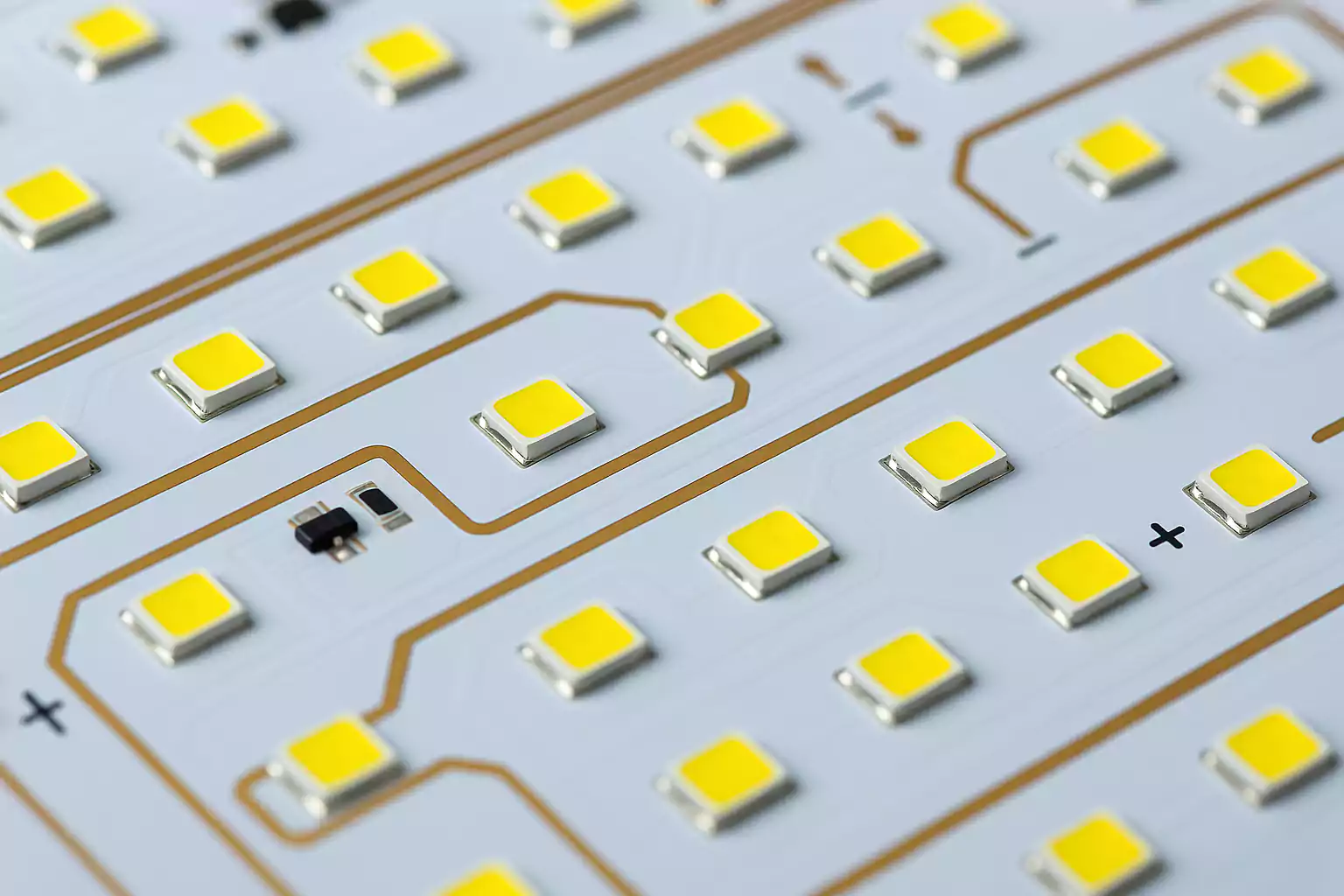
When you look inside a modern light bulb, a streetlamp, or even a car headlight, you’ll often find a small white board holding tiny yellow chips.
That board is a LED PCB — the hidden platform that makes LED lighting possible.
It connects the LEDs electrically, supports them mechanically, and moves the heat away so they can shine bright for years.
This guide explains what an LED PCB board is, why it’s different from a regular circuit board, the main types and materials used, and what to check before you order or test one.
What Is a LED PCB Board?
A LED PCB board (also called an LED light circuit board) is a printed circuit board designed specifically for mounting and powering light-emitting diodes.
It provides electrical connections, mechanical support, and thermal conduction — three things every LED needs to work safely.
Unlike common FR-4 PCBs used in electronics, LED boards handle much higher temperatures.
LEDs convert most of their input power into heat, and if that heat isn’t removed, brightness drops and the LED’s life gets shorter.
That’s why many LED PCBs use metal-core substrates that spread heat quickly to a heatsink or metal housing.
Why LED Boards Use Metal-Core (Aluminum) PCBs
Regular FR-4 glass-epoxy boards work fine for low-power indicator LEDs, but they can’t handle the heat of modern high-power lighting.
To solve this, engineers use metal-core PCBs (MCPCBs) — most often made with aluminum as the base metal.
The aluminum layer acts like a built-in heatsink.
Below the copper traces, there’s a thin dielectric layer that transfers heat while keeping electrical isolation.
This structure moves heat from the LED junction into the metal base and then to the air or an external heatsink.
Advantages:
- Excellent thermal conductivity (about 5–10x better than FR-4)
- Lower operating temperature and longer LED life
- Rigid and durable structure
Limitations:
- Slightly higher cost
- Not suitable for multi-layer or high-density signal routing
For most high-power LED lamps, floodlights, and car lights, aluminum PCBs are the default choice.
Main Types of LED PCBs and Where They’re Used
Not every LED board is the same.
• Rigid FR-4 LED PCBs
Used in low-power or indicator applications such as control panels and simple light modules.
They are inexpensive and easy to manufacture but have limited thermal performance.
• Metal-Core (Aluminum or Copper) PCBs
The most common choice for medium- and high-power lighting.
Aluminum cores handle power up to several watts per LED; copper cores are used in extreme-power or precision optical modules.
Typical uses: floodlights, headlights, COB modules, UV or IR lamps.
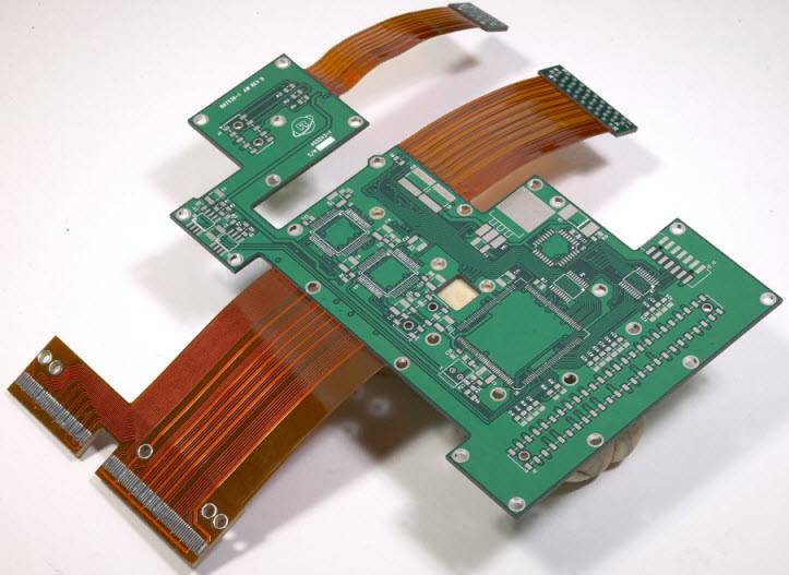
• Flexible (FPC) LED PCBs
Made from polyimide film, these bend easily and can be cut into long shapes.
They’re the base of LED strip lights and flexible backlights.
FPCs dissipate less heat, so they’re usually used with low-current LEDs or backed by aluminum extrusion for cooling.
• Hybrid or Multi-Layer Boards
Combine FR-4 and metal cores or stack multiple layers for control circuits, drivers, or sensors in one module.
Found in automotive and professional lighting systems.
| Type | Typical Thickness | Copper Weight | Application |
|---|---|---|---|
| FR-4 | 1.0–1.6 mm | 1 oz | Indicators, panels |
| Aluminum MCPCB | 1.0–1.6 mm | 1–3 oz | Lamps, bulbs |
| Copper base | 1.0–2.0 mm | 2–3 oz | High-power LEDs |
| FPC | 0.1–0.3 mm | 1 oz | LED strips |
| Hybrid | Custom | 1–3 oz | Automotive modules |
Key Materials and Appearance Choices
• Base Material
- Aluminum base: best balance of cost, weight, and heat spreading.
- Copper base: top thermal performance, used when heat load is extreme.
- FR-4: cheapest, good for small or indicator lights.
• Solder Mask Color
White is standard for LED PCBs because it reflects light and improves brightness uniformity.
Good white solder mask must resist yellowing during reflow or long-term heating.
• Surface Finish
LED boards often use ENIG (Electroless Nickel Immersion Gold) for flatness and corrosion resistance, or OSP for cost-sensitive products.
Immersion tin is also common for strip boards.
Thermal and Electrical Design Basics
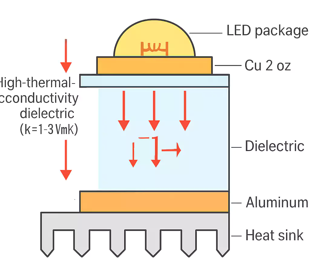
• Understanding the Heat Path
Heat travels from the LED’s junction → solder pad → dielectric layer → metal base → heatsink → air.
Each step adds thermal resistance.
Lower total resistance means a cooler LED and longer life.
• Copper Thickness and Trace Width
High-current LEDs need thicker copper (2–3 oz) or wider traces to avoid voltage drop and overheating.
Thermal spreading copper areas under or around LED pads help equalize temperature.
• Thermal Vias vs. Direct Heat Path
FR-4 boards use thermal vias (arrays of plated holes) to conduct heat to the bottom layer.
MCPCBs don’t need them — the metal core itself carries heat.
• Grounding and Driving
Every LED circuit needs a stable ground as a reference and return path.
Proper grounding prevents flicker, EMI noise, and ESD damage.
Use constant-current drivers for brightness stability; simple resistors work only for small indicator LEDs.
• Optical Uniformity
Keep equal spacing between LEDs and precise solder mask openings to maintain consistent brightness.
Avoid color difference by controlling pad tolerance and solder thickness.
Typical Specification Reference Table
| Parameter | Common Value | Notes |
|---|---|---|
| Board thickness | 1.0 mm / 1.2 mm / 1.6 mm | Standard MCPCB options |
| Copper thickness | 1–3 oz | 2 oz typical for power LEDs |
| Dielectric layer | 75–150 µm | High thermal conductivity (1–3 W/m·K) |
| Min trace / space | 6 mil / 6 mil | Standard production limit |
| Min hole | 0.3 mm | For mechanical mounting |
| Solder mask | White, high-reflectivity | Non-yellowing formulation |
| Warpage | ≤0.5% | Critical for long bars |
| Surface finish | ENIG / OSP / Imm. Tin | Depending on design |
Common LED PCB Applications
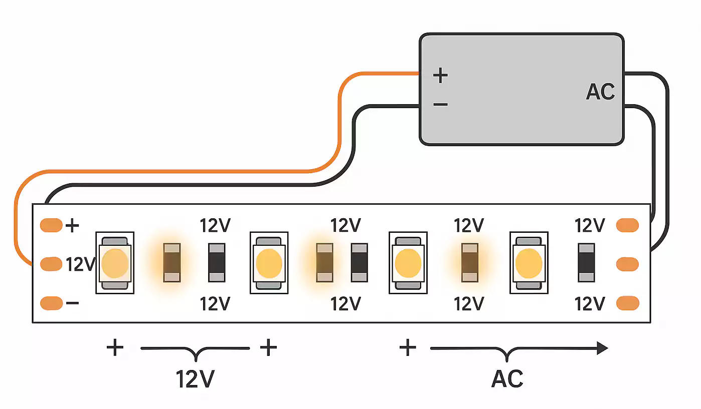
• LED Strip and Bar Lights
These use long, narrow boards with many series LEDs.
Designers often join multiple sections through V-cut lines or connectors.
Pay attention to voltage drop along the length; supply power every half-meter for uniform brightness.
• Automotive and Outdoor Lighting
High-power modules must handle vibration, moisture, and heat.
They often use integrated aluminum housings as both chassis and heatsink.
Protect the board with conformal coating or silicone to prevent corrosion.
• Medical and Industrial Lighting
Used where reliability and color accuracy matter — surgical lamps, inspection lights, UV curing.
These require consistent thermal performance and clean surfaces free of flux residue or scratches.
DFM Checklist for Prototyping and Mass Production
Good design-for-manufacture (DFM) practices prevent costly rework later.
Before you send files to your PCB supplier, check these points:
1.Files and Documents
- Provide Gerber, coordinate (XY), and BOM files.
- Add clear polarity marks for LEDs and any connectors.
2.Solder Mask and Silkscreen
- Verify white solder mask openings around LED pads to avoid contamination.
- Make sure the legend text doesn’t cover pads or fiducials.
3.Panelization and Handling
- For long or thin boards, use V-cut or tab-routing with break-tabs.
- Add tooling holes and fiducials for pick-and-place accuracy.
4.Reflow and Temperature Control
- Use a controlled profile below 250 °C to prevent yellowing or warpage.
- Test small batches first, especially when using large COB LEDs.
5.Functional and Aging Tests
- Light-up each board after assembly.
- Run a short aging test (e.g., 8–12 hours at rated current) to catch early failures.
These steps ensure stable color, brightness, and lifetime across your production batch.
Frequently Asked Questions (FAQ)
Q1: What is a LED PCB board?
A LED PCB is a circuit board optimized for LEDs.
It connects and powers LEDs while managing the heat they generate.
Most are made on aluminum or other metal-core materials.
Q2: Do LED lights have PCBs?
Yes. Nearly every modern LED lamp or strip uses a PCB to mount the LEDs, drivers, and resistors.
Even “bulb-type” LEDs contain a small aluminum board inside the housing.
Q3: Why do LEDs on PCB need ground?
The ground acts as the electrical reference and current return path.
Without it, the circuit becomes unstable, causing flicker or possible failure.
Ground planes also help reduce noise and static discharge.
Q4: What do LED and PCB stand for?
- LED: Light-Emitting Diode
- PCB: Printed Circuit Board
Q5: Can I use FR-4 instead of aluminum?
For low-power indicator LEDs, yes.
But for high-power or continuous lighting, FR-4 overheats easily.
Use aluminum MCPCB or add thermal vias and an external heatsink.
Conclusion
LED technology keeps evolving, but the printed circuit board beneath every LED is still the key to performance and lifetime.
A well-designed LED PCB board controls heat, supports stable current, and maintains consistent brightness across thousands of cycles.
When you design or order an LED light PCB, start with your power level and thermal target, then choose the right material, copper weight, and surface finish.
