As lead-free solder becomes the global standard, traditional FR-4 materials face new thermal and reliability challenges. To withstand higher reflow temperatures, most PCB laminate manufacturers have moved away from dicyandiamide (DICY) curing systems toward phenolic-based or alternative curing agents. These new Lead-Free FR-4 materials not only change thermal behavior, but also affect dielectric properties—especially at high frequencies.
This technical blog takes a deep dive into how curing systems affect the electrical performance of Lead-Free FR-4, comparing DICY-cured, phenolic-cured, and modified non-DICY/non-phenolic laminates, and exploring their performance in high-speed and RF applications.
The Shift in Curing Systems for Lead-Free FR-4
Traditional FR-4 laminates use DICY-cured epoxy systems, which offer low dielectric constant (Dk) and low dissipation factor (Df)—ideal for signal integrity.
However, lead-free compatible FR-4 laminates often use phenolic or phenol-formaldehyde curing agents instead.
- DICY-Cured Systems – Provide excellent electrical properties and stability across common frequencies; standard in legacy FR-4.
- Phenolic-Cured Systems – Offer better thermal stability and resistance to delamination, but show higher dielectric loss at high frequency.
- Modified (Non-DICY / Non-Phenolic) Systems – Developed to achieve both high Tg and superior high-frequency electrical performance for lead-free solder processing.
While phenolic-cured systems meet the thermal requirements of lead-free soldering, the different resin chemistry tends to yield higher Df values than DICY-based materials. At low frequencies, this difference is negligible—but as operating frequencies climb into the GHz range, these variations have a significant impact on impedance control and signal integrity.
Comparative Electrical Performance
Table 6.8 compares five FR-4 laminates:
- A, C: Traditional DICY-cured FR-4
- B, D: Phenolic-cured, lead-free compatible FR-4
- E: Modified lead-free FR-4 (non-DICY/non-phenolic)
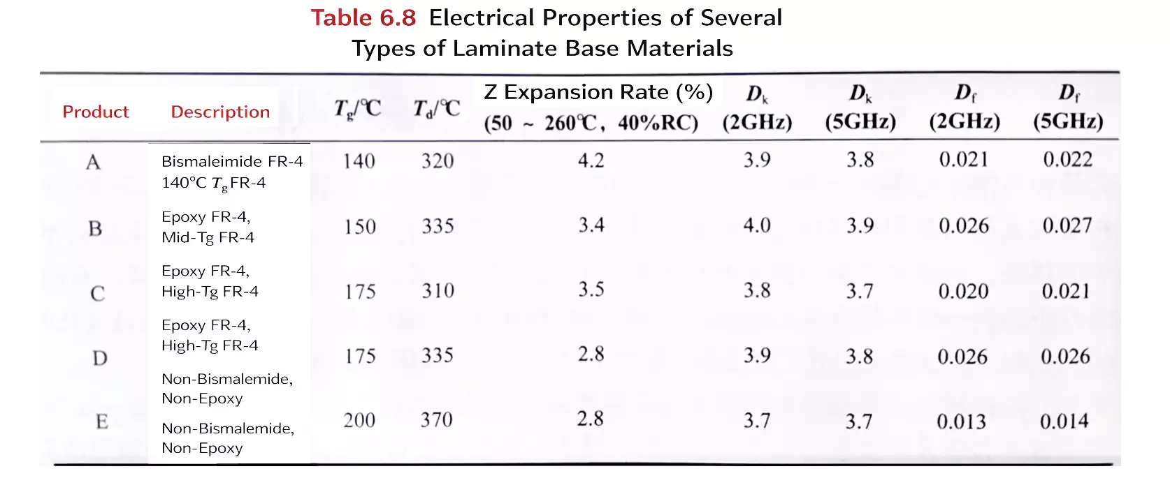
Under identical test methods and resin contents, results show:
- Phenolic-cured FR-4 materials have higher Df than DICY-cured ones at high frequencies.
- Material E matches or exceeds the thermal performance of phenolic FR-4 and achieves lower Dk and Df, outperforming even traditional DICY-cured FR-4.
- Optimized resin systems can combine excellent thermal reliability with improved dielectric properties in lead-free FR-4 laminates.
Because dielectric measurements can vary by test method, resin content, and reinforcement type, the relative trend in Table 6.8 is more meaningful than the absolute values.
High-Frequency Dk and Df Behavior
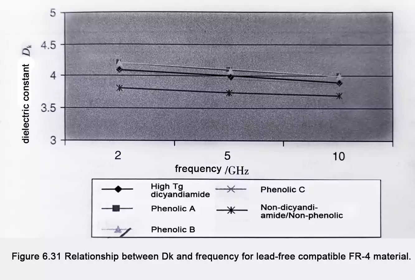
Separated cavity resonator testing shows clear trends at high frequency:
- Lead-free FR-4 materials using phenolic curing systems show higher Dk and Df than standard high-Tg DICY FR-4 at frequencies above several GHz.
- Phenolic-cured systems exhibit a wide range of Df values, indicating stronger dependence on resin formulation.
- Non-DICY/Non-Phenolic materials exhibit lower, more stable Df values with slightly reduced Dk, making them ideal for high-speed and RF PCB designs that require compatibility with lead-free solder processes.
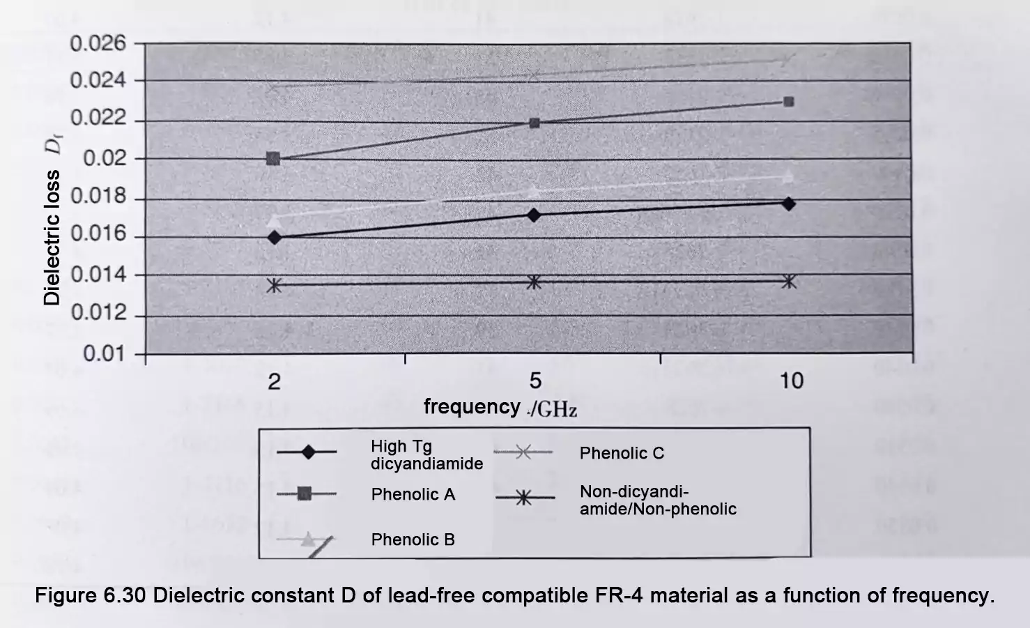
In essence, as frequency increases, even small differences in dielectric parameters become critical for impedance accuracy, signal loss, and EMI control.
Effect of Resin Content and Formulation on Dk
Table 6.9 provides Dk data (2–5 GHz) for one phenolic-cured FR-4 material under varying resin contents and formulations.
Key insights include:
- Higher resin content typically lowers the overall Dk, since epoxy resin has a lower dielectric constant than glass fiber.
- Different resin formulations result in measurable variations in Dk, driven by crosslink density and polymer structure.
- For precise impedance modeling, designers must account for pressed stackup values—actual resin distribution and glass weave type—not just nominal data sheets.
Dielectric Loss Behavior of Phenolic FR-4
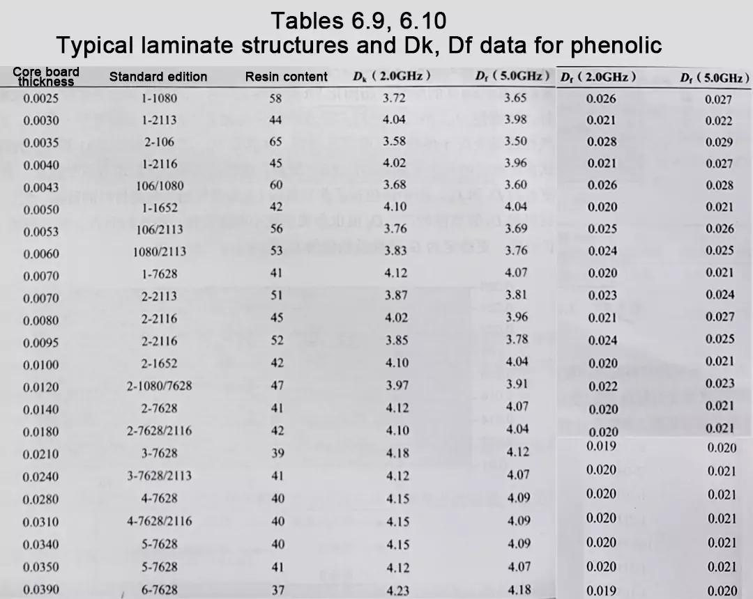
Table 6.10 presents Df (2–5 GHz) for the same phenolic material formulations:
- Df tends to increase slightly with frequency.
- Variations in resin content cause noticeable shifts in Df, showing that microscopic resin structure plays a key role in polarization loss.
- For applications like DDR5, PCIe Gen5/6, or 5GHz Wi-Fi, choosing a low-Df, lead-free FR-4 laminate is essential to preserve signal amplitude and open eye diagrams.
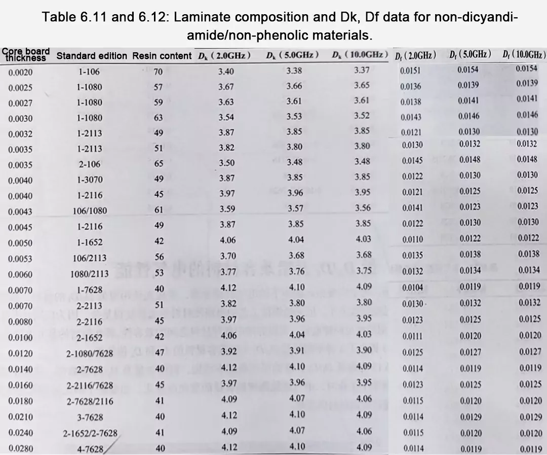
Non-DICY / Non-Phenolic Materials at 10 GHz
Tables 6.11 and 6.12 summarize data for modified non-DICY/non-phenolic materials at 10 GHz:
- These laminates maintain low and stable Df and consistent Dk values even at very high frequencies.
- Compared to conventional high-Tg FR-4, they deliver lower signal attenuation and tighter phase control.
- This makes them ideal for 5G base stations, automotive radar, and high-speed computing boards using lead-free solder technology.
Key Takeaways and Design Guidelines
- Curing System Defines Electrical Behavior
- Phenolic-cured materials offer thermal robustness but at the cost of higher Df.
- Modified non-DICY/non-phenolic systems balance both heat resistance and electrical performance for lead-free FR-4.
- High-Frequency Differences Amplify
- Above 2 GHz, even small changes in Dk or Df significantly affect impedance and signal loss.
- Consistent Test Conditions Are Essential
- Always compare materials tested with identical methods and resin content. Focus on trends, not absolute numbers.
- Collaborate with Material Suppliers
- Request frequency-dependent Dk/Df curves for the pressed stackup to ensure accurate signal integrity simulation.
Conclusion
The transition to lead-free solder processes has redefined the chemistry of FR-4 laminates. Modern Lead-Free FR-4 materials are no longer generic—they vary widely in resin systems, dielectric stability, and high-frequency loss.
The direction is clear: the industry is moving toward high-Tg, low-Df, lead-free FR-4 materials. Modified non-DICY/non-phenolic laminates represent the next generation, combining the thermal endurance required for lead-free soldering with the superior electrical performance demanded by today’s multi-gigabit designs.