


Changing the board size in NI Ultiboard is one of the first things you do when starting or revising a PCB design. Whether you’re shrinking a test board, expanding space for connectors, or matching a custom enclosure, resizing the board outline properly saves time and avoids rework later.
In this step-by-step guide, you’ll learn four simple ways to change PCB size in Ultiboard — from quick drag-and-drop to precise numeric control.
What You’ll Do in This Guide
Here are three things:
- Select the board outline (Board Outline layer)
- Resize it using properties, drag handles, or import a shape.
- Check and export the files before sending them to your PCB manufacturer.
Method A – Change Dimensions in Board Properties (Most Accurate)
This is the easiest and most precise way to resize a standard rectangular board.
Steps:
- Open your PCB file in Ultiboard.
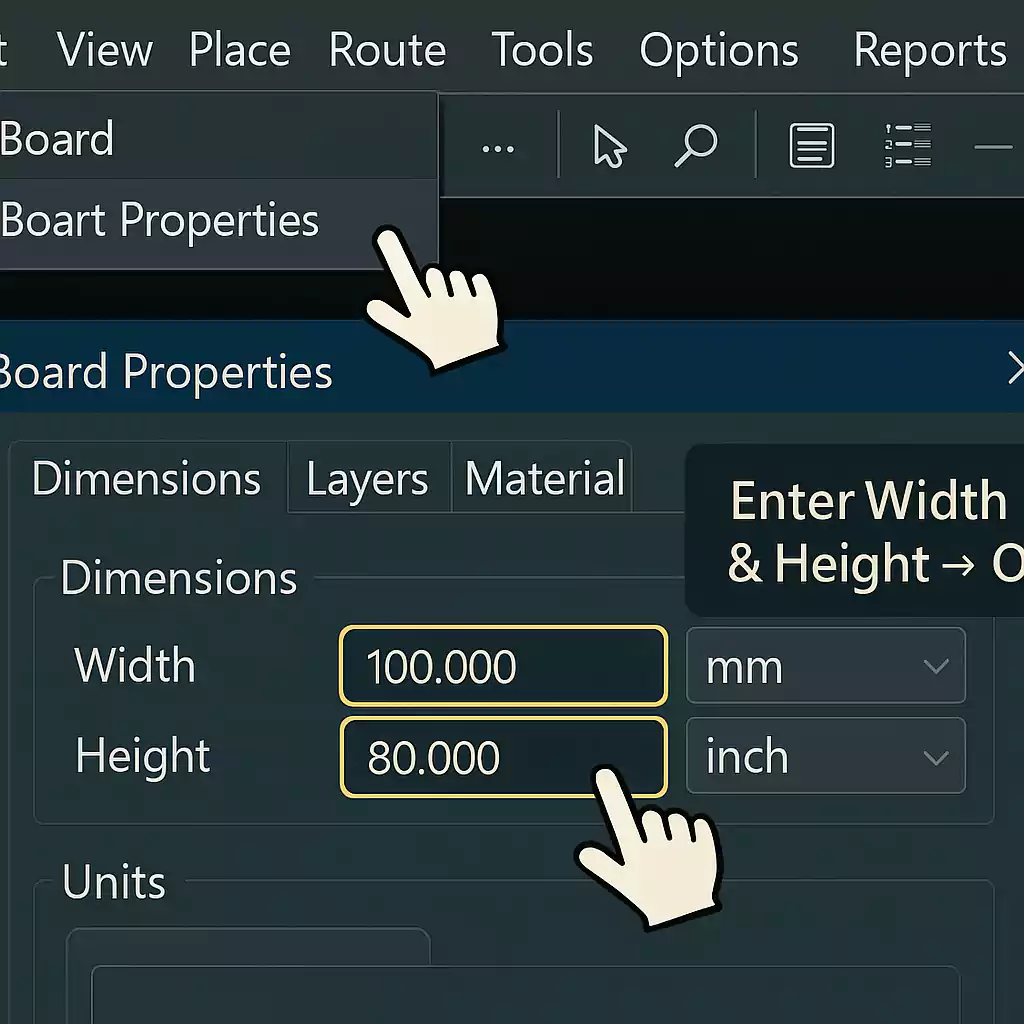
- Go to the top menu: Board → Board Properties.
- In the dialogue box, you’ll see options for Width, Height, and Units.
- Enter your new values (for example, from 100 mm × 80 mm to 90 mm × 70 mm).
- Click OK to apply changes.
The board outline will instantly resize.
If you need to switch from inches to millimetres, select the correct unit from the same window before entering values.
Set the board origin (0,0) at the bottom-left or centre of your enclosure. It helps keep dimensions consistent when exporting mechanical drawings or aligning with 3D models.
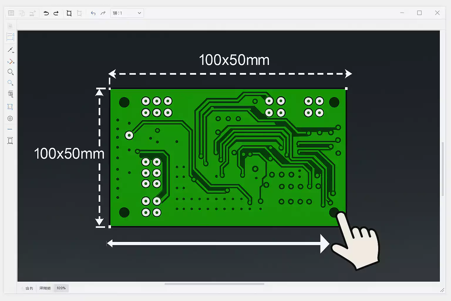
Method B – Drag the Edges or Corners (Fast and Visual)
Sometimes you don’t need to type numbers — you just want to adjust the shape a little.
Ultiboard lets you resize directly with the mouse.
Here’s how:
- Select the Board Outline in the Design Toolbox or click the board edge.
- Small handles appear around the outline.
- Click and drag an edge or corner to enlarge or shrink the board.
- Release the mouse to confirm.
You’ll see real-time movement as you drag.
If snapping feels off, check Options → PCB Properties → Grid to adjust grid spacing.
Turn on Snap to Grid for cleaner movements. It helps keep holes, connectors, and copper areas aligned with your board edge.
Method C – Use the Board Outline Wizard or Import DXF (For Accurate Shapes)
If your product has a defined mechanical enclosure or if your mechanical engineer already provided a drawing, you can use Ultiboard’s built-in tools to match it exactly.
Option 1: Board Outline Wizard
- Go to Board → Board Outline Wizard.
- Follow the on-screen steps to choose a basic shape (rectangle, rounded rectangle, circle).
- Enter your desired dimensions, and Ultiboard automatically creates the outline.
Option 2: Import DXF
- Choose File → Import → DXF.
- Select your mechanical drawing (often exported from SolidWorks or AutoCAD).
- Make sure the units match (mm or inch).
- The imported DXF becomes your new board outline.
Method D – Redraw the Board Outline (For Custom Shapes)
If your board isn’t a perfect rectangle — for example, it has curves, slots, or cutouts — you can redraw the outline manually.
To do it:
- Select and delete the old outline (press Delete after selecting).
- Choose the Board Outline layer.
- Use the Line and Arc tools to draw a closed polygon following your desired shape.
- Once closed, the new outline becomes your active board edge.
This gives you full creative control. Just make sure all lines connect properly — open shapes can cause manufacturing errors.
After Resizing: 10-Point Quick Check Before Export
Changing board size can affect other parts of your design. Before you generate new Gerber files, take 2 minutes to review this checklist.
- Units: Confirm you’re using the correct unit system (mm vs. inches).
- Origin: Move the board origin if needed to align components and mechanical drawings.
- Edge clearance: Ensure components, copper pours, and text stay safely within the new edges (usually 0.5–1.0 mm).
- Mounting holes: Recheck positions; resizing can move them closer to the border.
- Silkscreen: Ensure part labels and logos don’t overlap or fall off the edge of the board.
- Copper pours: Use Update Copper Areas (or Repour) to refresh ground and power planes.
- Traces: Zoom in and verify that traces near the edge haven’t been cut off.
- Vias and slots: Confirm they’re still inside the board boundary.
- Power and ground nets: Check that large traces still handle the expected current.
- Export preview: Generate Gerber and drill files, then open them in a viewer to confirm the shape is closed and correct.
Doing this small review step prevents costly board re-runs or delays during manufacturing.
Frequently Asked Questions (FAQ)
Q1. How do I change board size in Ultiboard?
Go to Board → Board Properties and edit Width and Height.
For minor changes, select the outline and drag it with the mouse.
For complex shapes, use the Board Outline Wizard or import a DXF drawing.
Q2. How do I change the trace width in Ultiboard?
Double-click the trace you want to modify.
In the Properties window, change the Width value.
To apply it to multiple nets, open Design Rules → Nets, and set the default trace width there. Then reroute or update your tracks.
Q3. How do I adjust board size in Altium?
In Altium, go to Design → Edit Board Shape and drag or redefine the outline.
The concept is similar: the board outline defines the physical PCB boundary.
If you’re switching between tools, always double-check dimensions after import/export.
Q4. How can I make my PCB smaller overall?
You can reduce the total board area by:
- Using smaller packages (for example, SMD instead of through-hole)
- Tightening component spacing (but respect minimum clearances)
- Moving connectors and mounting holes efficiently
- Using a multi-layer board if you run out of routing space
- Removing unnecessary copper or test pads
Example: Resize a 100 × 80 mm Board to 90 × 70 mm
Let’s walk through a quick real-world example.
- Open your project in Ultiboard.
- Go to Board → Board Properties.
- Change the Width from 100 mm to 90 mm and the Height from 80 mm to 70 mm.
- Click OK — your outline updates instantly.
- Move components slightly if needed so they’re not too close to the edge.
- Right-click copper areas and select Update Copper Areas to refill them.
- Run Design → Verify Design Rules to make sure nothing violates spacing.
- Export new Gerber and Drill files.
Open them in your preferred Gerber viewer (like ViewMate or Gerbv) to confirm the final shape.
If everything looks good, your board is ready for manufacturing.
Send Your Updated Design to FastTurn PCBs
Once you’ve resized and checked your board, you can upload your Gerber and drill files directly to FastTurn PCBs for instant online quoting.
Here’s what you get:
- Quick-turn prototypes with 24-hour or 48-hour options
- Full PCBA service — just upload your BOM and pick-and-place file
- Free engineering review before production to catch outline or drill errors
Whether it’s a one-off prototype or small-batch build, FastTurn PCBs helps you go from design to finished board faster.
Final Thoughts
Changing the board size in Ultiboard isn’t hard — you just need to know which method works best for your situation.
- Use Board Properties for precise rectangles.
- Use dragging for quick adjustments.
- Use the wizard or DXF import for complex mechanical outlines.
- And always verify your design before sending it out.
Once your PCB layout looks good, get it fabricated and assembled in one place.
FastTurn PCBs provides prototype, quick-turn, and assembly services with professional file checks — so you can focus on design, not delays.
