Introduction
In the world of printed circuit board (PCB) design and materials engineering, Glass Transition Temperature (Tg) is a foundational concept. Choosing the right Tg for your laminate or prepreg can mean the difference between a reliable board and one that warps, delaminates, or fails under thermal stress. In this article, you'll get a clear understanding of what Tg means, how it affects PCB reliability, how it's measured, and practical advice on selecting the right Tg class for your application.
1. What Is Glass Transition Temperature (Tg)?
1.1 Basic Definition & Molecular Perspective
Glass transition temperature, commonly denoted Tg, is the temperature range where an amorphous (or semi‑amorphous) polymer transitions from a hard, "glassy" (rigid) state to a softer, rubber‑like or more mobile state. Below Tg, molecular chains in the polymer matrix are effectively "frozen" — they cannot rearrange freely. As temperature increases through Tg, local chain segments begin to move, increasing free volume, lowering modulus, and increasing thermal expansivity.
Because Tg is a kinetic phenomenon, not a sharp thermodynamic phase transition, its precise point depends on heating/cooling rates, measurement method, and the degree of cure of the polymer.
1.2 Glassy vs Rubbery vs Liquid States
- Below Tg: The material is stiff, brittle, dimensionally stable, and behaves more like a glass.
- Near Tg: The modulus and thermal expansion coefficient change rapidly.
- Above Tg (but below decomposition/melting): The matrix becomes more compliant, molecular chains have more mobility, the material behaves more "rubbery."
The Tg is always lower than the melting temperature (Tm) of semi‑crystalline domains, when they exist.
In the PCB context, exceeding Tg doesn't "melt" the substrate, but it can degrade mechanical stiffness and dramatically increase expansion.
2. Why Tg Matters for PCBs: Stability, Stress, & Reliability
Tg in a PCB is more than just a number—it underpins how the composite (glass + epoxy + copper) will behave under thermal cycles, soldering, and long‑term operation.
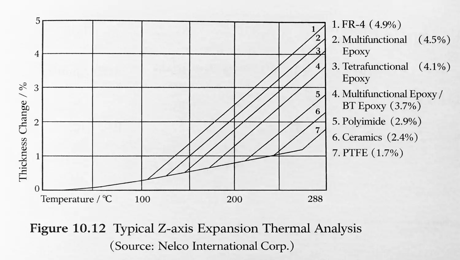
2.1 Thermal Expansion & Stress Mismatch
Below Tg, CTE (Coefficient of Thermal Expansion) of the epoxy/glass matrix is relatively modest and somewhat controlled. But as temperature approaches Tg, the epoxy’s expansion coefficient can jump. Because copper and glass fiber reinforcement partially constrain expansion, much of the expansion stress is translated into the Z-axis direction (thickness) and through-hole (PTH) region.
If a board repeatedly cycles above Tg, the accumulated stress can lead to delamination, cracks in vias, or breakage of plating.
2.2 Dimensional Stability & Warpage
High Tg materials tend to be more dimensionally stable under high temperature stress. Boards made with low Tg resins may warp or creep under extended high thermal load. This is especially problematic in HDI (high density interconnect) or fine‑pitch designs, where small deformation can misalign traces or components.
2.3 Reliability During Soldering & Assembly
During reflow or wave soldering, PCBs may see localized hot spots exceeding 150 °C or more. If Tg is too low, parts of the board may soften or distort during assembly—leading to misregistration, delamination, or circuit shifts. High Tg provides a buffer during the harsh thermal stress of soldering.
2.4 Long-Term Aging & Degradation
Over time, polymers undergo mechanical, thermal, and chemical aging. A higher Tg often correlates with improved thermal stability and slower degradation under elevated temperatures, which is especially beneficial in high-reliability, long-lifetime electronics.
3. Measuring Tg: Methods, Differences, and Pitfalls
Because Tg is somewhat subjective (measurement‑dependent), for PCB laminates you’ll typically see values determined by one or more of the following methods:
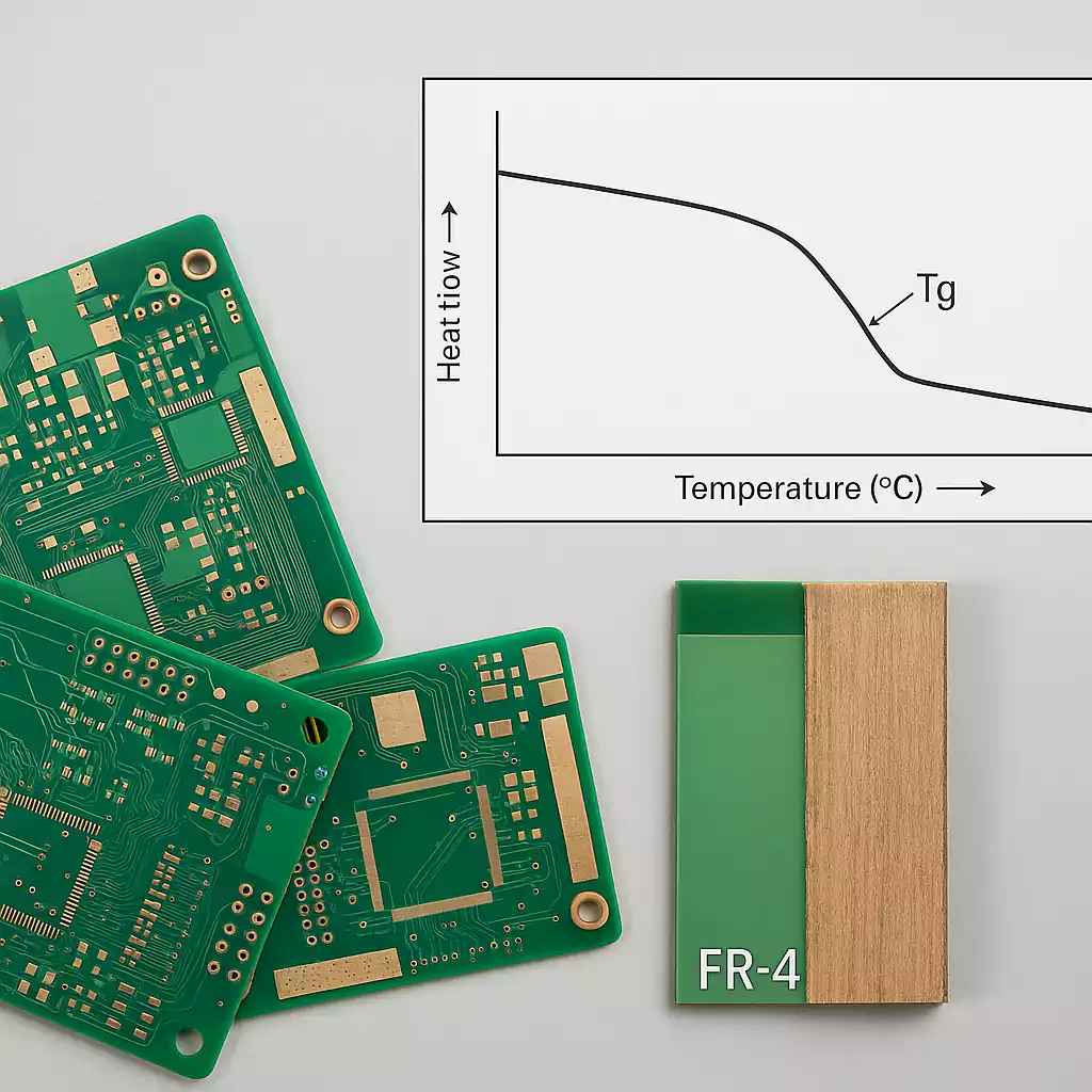
3.1 DSC (Differential Scanning Calorimetry)
- Measures heat flow as the sample is heated.
- You see a "step" in heat capacity around Tg.
- Often reported as the midpoint of that step.
- Advantage: well standardized (ASTM E1356, etc.).
- Caveat: small sample size, doesn't directly measure mechanical behavior or dimensional change.
3.2 DMA (Dynamic Mechanical Analysis)
- Measures mechanical modulus (storage/loss modulus) as a function of temperature/frequency.
- Tg often taken at the peak of the loss modulus or tan δ.
- Better correlates with mechanical performance (stiffness drop).
- Different frequencies can shift the observed Tg.
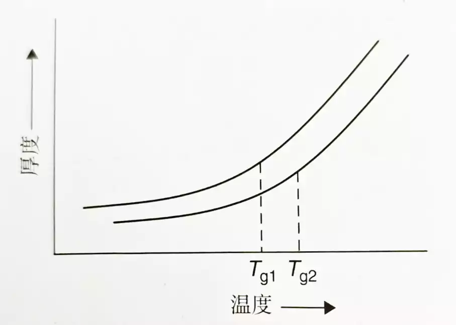
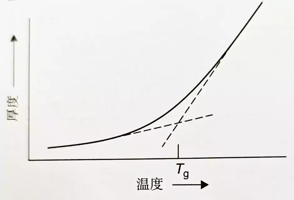
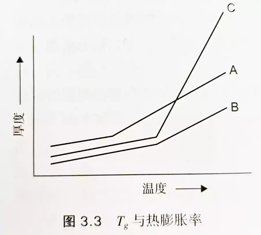
3.3 TMA (Thermo‑Mechanical Analysis) / TMA Dilatometry
- Measures dimensional change (expansion) vs temperature, detecting a change in slope at Tg.
- Captures physical expansion behavior rather than heat flow or mechanical modulus.
Because these methods measure different phenomena (heat capacity shift vs modulus vs expansion), the reported Tg values can differ by 10–20 °C or more for the same material.
Additionally, Tg depends on:
- Degree of cure — undercured resin will show a lower Tg.
- Heating / cooling rates — faster rates shift Tg upward.
- Sample history and moisture content — water acts as a plasticizer and lowers Tg.
4. Selecting Tg for PCB Design: Guidelines & Tradeoffs
When choosing Tg for a board, you must balance reliability, performance, and cost.
4.1 Rule-of-Thumb Margin
A common guideline is to choose a Tg value that is 20–30 °C higher than the highest operating temperature of your device. This gives a safety buffer against thermal spikes, drift, or measurement uncertainty.
For example, if your device can reach 125 °C, you might look for a Tg of at least 155–160 °C.
4.2 Standard, Mid, High Tg Ranges
- Standard FR‑4: Tg ~ 130–140 °C
- Mid Tg: ~150–160 °C (often used when moderate thermal performance is needed)
- High Tg: ≥ 170–180 °C or more
4.3 Tradeoffs & Caveats
- Cost: Higher Tg resins are more expensive and may require more precise processing (control of cure temperature, handling).
- Adhesion / toughness: As Tg increases, the polymer may become more brittle, reducing toughness or adhesion (especially copper-to-laminate adhesion) under shock or mechanical stress. Some suppliers caution that high Tg may decrease adhesion strength.
- Process complexity: Higher Tg resins might require longer cure times, tighter temperature control, or more refined prepreg stacking to avoid delamination during lamination.
- Compatibility with other materials: The thermal expansion mismatch with copper, vias, or other layers is still critical.
5. Failure Modes & Mitigation: When Tg is Exceeded
Here are some illustrative ways things can go wrong when Tg is not properly accounted for — and how to mitigate:
5.1 Delamination & Interfacial Failure
If localized areas in the board exceed Tg during operation or reflow, the resin matrix softens and the bond between layers can weaken. Repeated cycles will fatigue the interface and cause delamination. This is especially risky near edges, cutouts, or vias.
Mitigation: Use resin systems with higher Tg and strong adhesion properties; design for gradual ramping in lamination; avoid extreme thermal gradients.
5.2 Plated Through Hole (PTH) Cracking / Cu Peel Failure
The expansion mismatch (especially Z-axis) above Tg can stress copper plating. Over time, plating or barrel cracks can form.
Mitigation: Ensure the Tg margin covers expected thermal excursions; optimize via geometry (annular ring, aspect ratio); use barrel finishing or reinforcement if needed.
5.3 Warpage & Misregistration
Boards that soften near Tg may warp or exhibit creep. For fine-pitch or HDI boards, even small deformation can misalign vias, BGA balls, or microvias.
Mitigation: Use stiffer laminate stackups, enforce symmetric layups, select high Tg in critical layers, limit temperature gradients in processing.
5.4 Cumulative Aging under High Heat
Even if a board never repeatedly cycles above Tg, operating near Tg for extended periods accelerates aging, softening, and microcracking.
Mitigation: Provide thermal management, derate heights, or select a Tg well above expected long-term temperatures.
FAQ: Common Questions About Tg in PCB Materials
What is Tg in PCB materials?
Tg (glass transition temperature) is the point where the PCB’s resin changes from rigid to soft. Below Tg, the material stays stable; above Tg, it becomes flexible and expands faster. This affects how well the board handles heat.
Why is Tg important in PCB design?
Tg affects how a PCB performs under heat. If Tg is too low, the board can warp, delaminate, or crack during soldering or operation. Choosing the right Tg helps ensure long-term reliability.
What Tg range should I choose for my board?
·Standard boards: 130–140 °
·High-performance boards: 170 °C or more
Pick a Tg at least 20–30 °C higher than your board’s highest operating temperature.
Is higher Tg always better?
Not always. High Tg improves thermal performance, but it may raise costs and reduce toughness or adhesion. Choose Tg based on your device’s actual heat exposure.
How is Tg measured, and why do values differ?
Tg can be measured using DSC, DMA, or TMA. Each method gives slightly different results because they measure different properties (heat flow, stiffness, expansion). That’s why datasheet Tg values can vary
Conclusion
- Tg is a dynamic transition region, not a sharp boundary. Different measurement methods yield different Tg values.
- In PCBs, Tg marks the region where the resin matrix begins to soften and expand more rapidly, potentially generating stress on vias, copper, and interfaces.
- Always choose a Tg margin (20–30 °C or more) versus your highest expected temperature.
- High Tg resins bring major benefits (dimensional stability, low expansion, resistance to thermal stress), but come with costs, processing complexity, and tradeoffs (toughness, adhesion).
- A well‑structured PCB design considers Tg alongside CTE, stackup, via layout, and thermal cycling.