When preparing Gerber files for manufacturing, even experienced designers sometimes run into preventable delays—most often because of incorrect layer usage. One repeated issue reported across PCB manufacturers is simple but costly: placing mechanical board outlines or cutouts on the GKO layer, which was never meant to convey physical fabrication data.
Understanding the difference between GKO, Mechanical layers, keep-out regions, and the true PCB outline is essential for clean CAM processing and error-free fabrication.
This guide clarifies those distinctions, explains why the confusion exists, and provides best practices so your Gerber package works the first time.
The Short Answer: Where Each Layer Belongs
| PCB Outline / Board Shape | Mechanical Layer (or dedicated Outline/Profile file) | GKO / Keep-out Layer |
| Cutouts, Internal Slots, Milling | Mechanical Layer | GKO |
| Component / Routing Restrictions | GKO (Keep-out) Layer | Mechanical |
| Manufacturing Notes, Dimensions | Mechanical Layer | GKO |
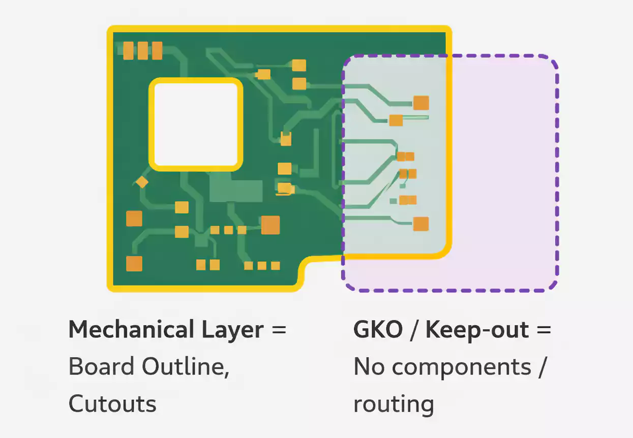
The GKO/Keep-out layer is a design constraint.
The Mechanical layer (or dedicated outline file) is a manufacturing instruction.
What Exactly Is the GKO Layer (Keep-out Layer)?
1. Purpose: A Design-Time Restriction Layer
The GKO layer—sometimes labeled “Keep-out” in CAD tools—is intended strictly for layout rules such as:
- Areas where no copper may be poured
- Zones where no components may be placed
- Boundaries where routing must not cross
- Regions reserved for mechanical restrictions or isolation
- Safety spacing zones within high-voltage or RF layouts
It exists to guide the designer and the DRC engine—not the PCB manufacturer.
2. What the GKO Layer Is Not
The GKO layer is not for:
- Physical board outlines
- Cutouts or milling shapes
- Mechanical dimensions
- Fabrication drawings
- Actual routing paths or drill instructions
If you put physical geometry on GKO, your manufacturer may:
- Completely ignore it
- Interpret it incorrectly
- Ask for clarification to delay your order.
- Produce a board in the wrong shape.
For manufacturers, GKO carries no authoritative weight.
Mechanical Layer: The Real Home for PCB Outline Data
1. What Belongs on the Mechanical Layer?
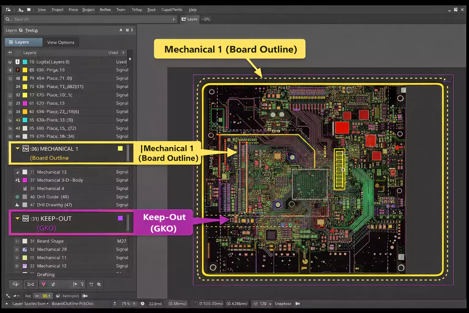
A Mechanical layer (e.g., “Mechanical 1”) or a dedicated Profile / Outline layer is where your PCB’s physical definition must live. This includes:
- PCB outline / board shape
- Internal cutouts
- Routing slots
- Milled features
- Mounting holes (if dimensioned)
- Tooling holes
- Mechanical notes
- Fabrication dimensions
- Connector keep-out envelopes (if needed by fab)
This layer communicates the actual geometry that the fabricator will cut.
2. Why Manufacturers Rely on Mechanical / Outline Layers
CAM engineers use the mechanical outline to:
- Generate routing paths
- Plan panelization
- Define breakaway tabs
- Perform automated dimensioning checks.
- Detect mismatched drill or copper expansion.
If the outline is missing or unclear, production cannot proceed.
PCB Outline in Gerber Files: How It Should Be Expressed
1. Minimum Requirements for a Valid PCB Outline
A proper PCB outline must be:
- Closed (start and end points meet exactly)
- Continuous (no tiny gaps or overlaps)
- Single and unambiguous (only one authoritative outline)
- Machine-readable (not text, not annotation marks)
- Placed on a mechanical or outline layer, not a keep-out
An incomplete or open outline is the #1 cause of CAM rejection.
2. Consolidate Mechanical Features in One Place
Manufacturers advise keeping all mechanical elements together.
When mechanical data is scattered across multiple layers:
- Some features may go unnoticed.
- Dimensions may conflict
- CAM operators must manually interpret your intent
If you must use multiple mechanical layers (e.g., Mechanical 1 for outline, Mechanical 13 for dimensions), include a README layer map.
3. Why You Sometimes See .GKO Used as an Outline File
Here’s where many designers get confused:
- The GKO file extension (e.g., boardname.GKO) is commonly used to denote an outline Gerber file, especially in legacy workflows (Protel, Protel-based toolchains, and some Chinese fabrication systems).
This leads to the false assumption:
“GKO layer” = “outline layer”
But the truth is:
- “GKO as keep-out layer” is a design semantics meaning.
- “.GKO as Gerber extension” is a file naming convention used by some fabricators.
They are not the same thing.
To avoid ambiguity, explicitly state in your documentation which file contains your official PCB outline.
Why Designers Confuse GKO and Mechanical Layers
Most ECAD tools allow designers to rename or reassign layer types freely.
As a result:
- A keep-out area might appear to be a mechanical element.
- An outline might be drawn on a keep-out layer by accident.
- A misconfigured export job might dump keep-out into a Gerber with a “.GKO” extension.
With inconsistent conventions (e.g., .GM1, .GKO, .GML for outlines), confusion is common.
This is why fabricators frequently request:
“Please label your Gerber layers clearly or include a layer map.”
The Risks of Putting Mechanical Information on GKO
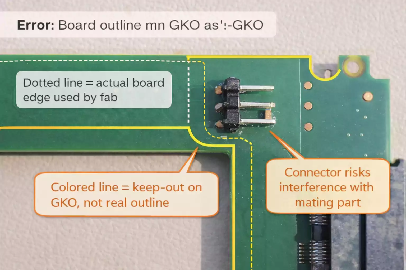
Placing PCB outlines or cutouts on the GKO layer is one of the quickest ways to delay fabrication. Typical issues include:
1. CAM May Miss the Outline Completely
Keep-out layers do not participate in routing or milling definitions.
If a CAM operator doesn’t expect a mechanical feature there, they will not extract it.
2. Manufacturing Errors from Misinterpretation
A misread outline can result in:
- Incorrect board dimensions
- Missing internal cutouts
- Wrong panelization strategy
- Misaligned drill patterns
3. Your Job May Be Placed On Hold
If the outline is unclear, CAM cannot proceed.
Fabricators will contact you to verify:
- Which layer defines the board shape
- Whether GKO is meant as an outline or as a keep-out
- Whether multiple outlines exist
Every clarification adds to the turnaround time.
4. Worst Case: Incorrectly Fabricated Boards
If the CAM operator assumes incorrectly, you may receive:
- Boards of the wrong size
- Missing milling features
- Invalid mounting hole positions
This can scrap an entire production batch.
Best Practices for Clean, Manufacturer-Ready Gerber Files
Below is a practical, fabrication-focused checklist that helps ensure your Gerber files work everywhere—from quick-turn prototyping services to advanced PCB factories.
1. Use the Correct Layers
- PCB outline: Mechanical layer or dedicated Outline/Profile layer
- Cutouts/slots: Mechanical layer
- Keep-out zones: Keep-out (GKO) layer
- Notes & dimensions: Mechanical layer
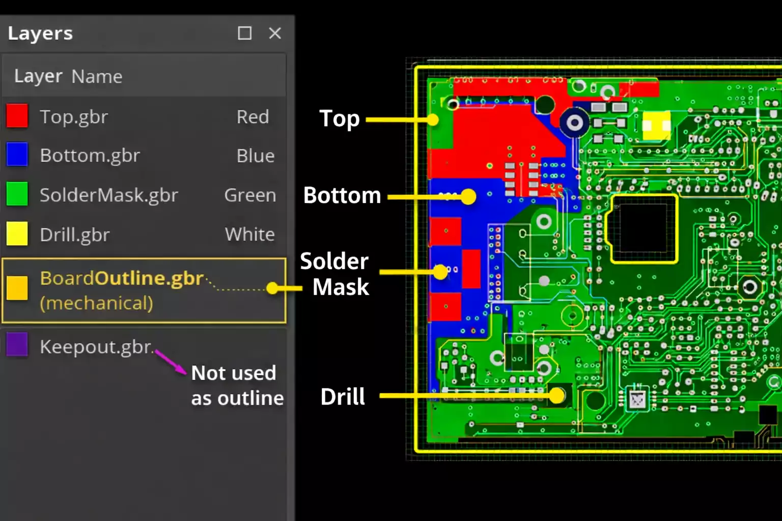
2. Name Your Gerber Files Clearly
Use labels like:
- boardname-Outline.gbr
- boardname-Mechanical1.gbr
- boardname-Keepout.gbr
Clarity eliminates guesswork.
3. Before Exporting, Double Check Layer Assignments
In your CAD tool, verify:
- Outline is on the correct layer.
- Keep-out has no mechanical geometry.
- Drill files match holes in mechanical data.
- There are no duplicates or conflicts in the outline.
4. Before Submitting, View Your Gerbers
Use a Gerber viewer (e.g., Gerbv, ViewMate, KiCad Viewer) to confirm:
- Outline appears once
- Cutouts appear exactly where expected.
- No unwanted features on GKO
- Layer registration aligns properly.
5. When in Doubt, Ask Your PCB Fabricator
Manufacturers in different regions and toolchains interpret Gerber file naming differently.
A 30-second question can prevent a 3-day delay.
FAQ: High-Search-Intent Questions Answered
Is the GKO layer always the keep-out layer?
In CAD tools, yes—GKO usually represents a keep-out region.
In Gerber manufacturing workflows.GKO may be a file extension for an outline.
This is why confusion exists.
Should the PCB outline be on the Mechanical layer?
Yes.
If your CAD tool supports a dedicated board profile or outline layer, that is acceptable too.
The critical rule: The outline must be clear, closed, and placed where the manufacturer expects it.
Do manufacturers accept outlines on copper or mask layers?
Some do, but you should avoid this practice.
It is prone to misinterpretation and is not industry best practice.
Where should cutouts and slots go?
On the Mechanical or Outline/Profile layer—never on GKO.
What happens if my outline is placed incorrectly?
Your order may be:
·put on hold
·delayed
·fabricated incorrectly
Mechanical inaccuracies are one of the most expensive PCB mistakes.
Final Thoughts
Getting Gerber layer usage right isn't just a matter of neatness—it directly affects turnaround time, yield, and final PCB quality. Keeping keep-out rules (GKO) and mechanical features properly separated eliminates ambiguity and ensures your manufacturer produces the exact board you designed.
At FastTurnPCB, we review every Gerber package with CAM-level detail to help customers catch defects early, reduce errors, and accelerate time-to-market.