What is Functional Circuit Testing (FCT)?
Functional Circuit Testing (FCT) is a final-stage testing method used in PCB assembly to verify that a completed circuit board performs its intended functions under real-world conditions. Unlike visual inspections or structural tests, FCT goes beyond ensuring that the board is physically intact—it confirms that the assembled PCB behaves as expected when powered and operating as part of a system.
During FCT, the board is typically energized, and actual electrical signals are applied to simulate normal operating conditions. The tester monitors outputs, current flow, voltage levels, and communication signals to ensure all components are working correctly and that the board’s firmware or embedded software responds as it should.
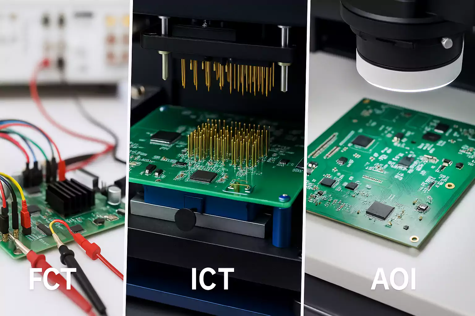
FCT is most commonly used after other quality control steps such as In-Circuit Testing (ICT), Automated Optical Inspection (AOI), and X-ray inspection. While those methods are excellent at catching soldering issues, shorts, or missing components, they can't guarantee that a board will function properly once deployed. FCT fills this critical gap by simulating real usage scenarios—making it a vital part of any high-reliability electronics manufacturing process.
In essence, FCT answers the most important question before a board leaves the factory: "Does it work?"
How Does Functional Testing Work?
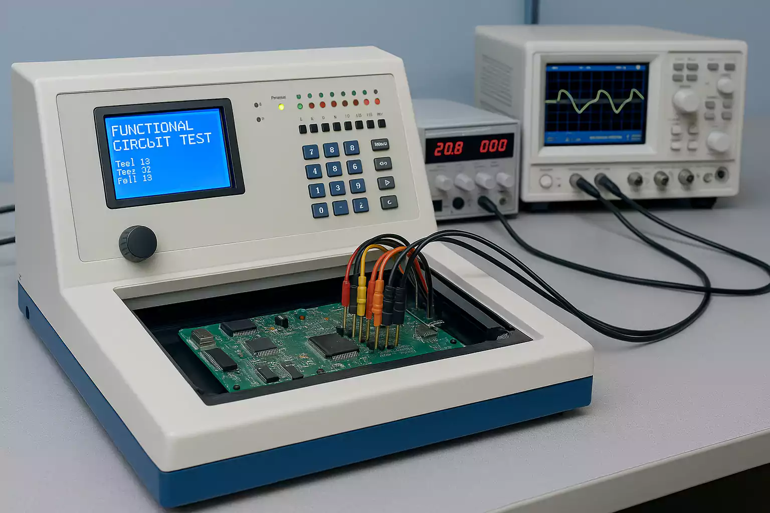
Functional Testing works by simulating how a printed circuit board (PCB) will operate once it’s fully assembled and deployed in the field. It involves applying real-world input signals and power to the board and monitoring its outputs to verify that every circuit and component performs correctly under expected operating conditions.
At its core, the functional test replicates the board’s actual use case. This is typically done using a functional test fixture and automated test software, which together deliver inputs and measure outputs like voltage, current, communication protocols, and logic states. The test may include checking power rails, verifying digital and analog signal paths, reading microcontroller responses, and ensuring software or firmware is correctly loaded and operational.
Step-by-Step Overview of the FCT Process:
- Power-On the Board
The PCB is connected to a power source to simulate normal operation. - Stimulate Input Interfaces
Signals such as button presses, communication inputs (e.g., UART, I2C, CAN), or sensor simulations are fed into the board. - Monitor Outputs
The tester checks for correct responses on output pins, connectors, displays, LEDs, relays, or communication ports. - Verify Functional Behavior
The system compares the board's behavior to predefined specifications or “golden board” standards to determine pass or fail. - Log Test Data
Detailed logs and test results are recorded for quality control and traceability.
What Does Functional Testing Detect?
- Incorrect firmware installation or failure to boot
- Malfunctioning ICs or passive components
- Communication errors (e.g., UART, SPI, I2C)
- Timing issues, output voltage errors, and logic faults
- Miswired connectors or reversed components that still pass structural tests
Why Automation Matters
Modern FCT setups often use programmable logic controllers (PLCs), embedded test software, or dedicated test stations to automate the process. Automation ensures repeatability, reduces human error, and speeds up production—especially critical for medium to high-volume PCB assembly.
What Equipment is Used in Functional Circuit Testing (FCT)?
Functional Circuit Testing (FCT) relies on a combination of mechanical fixtures, electronic instruments, and software systems to simulate real-world operating conditions and verify the performance of assembled PCBs. The choice of equipment depends on the complexity of the board, the type of functionality being tested, and the production volume.
Below are the core components commonly used in a typical FCT setup:
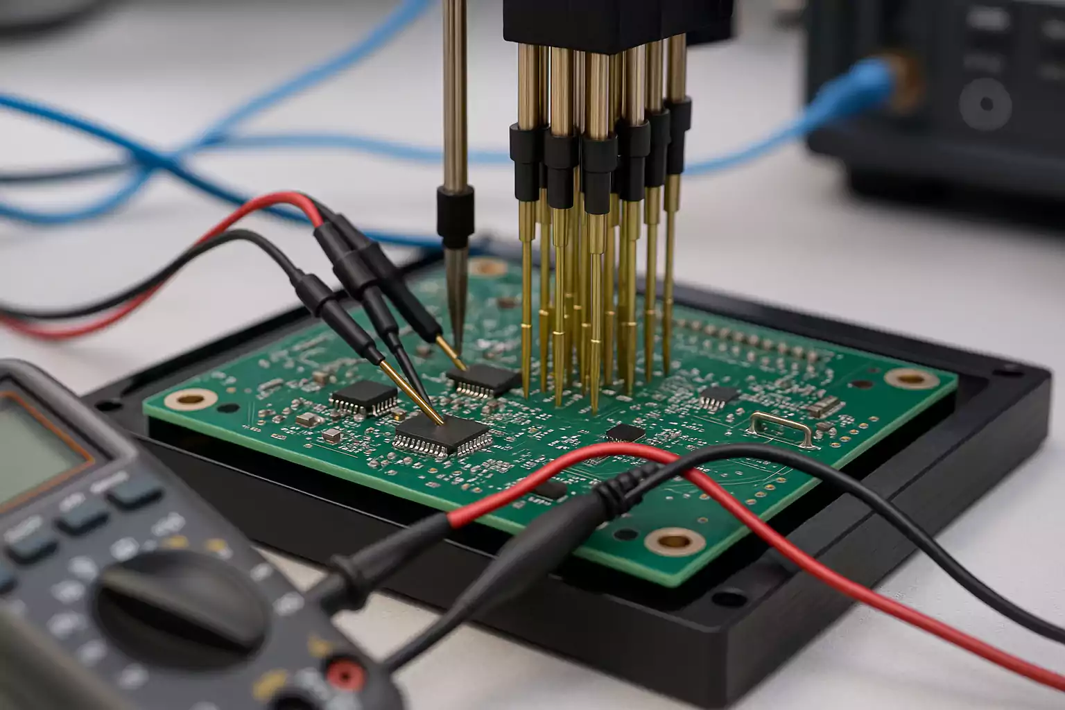
1. Functional Test Fixture
Also known as a bed-of-nails fixture, this is a custom-designed mechanical interface that physically connects the test system to the PCB under test. It uses spring-loaded pogo pins or probes to make contact with test points, pads, or connectors on the board.
Key features:
- Custom layout to match PCB test points
- Secure mounting to prevent movement during testing
- May include clamps, covers, or ESD protection features
Fixtures are essential for repeatable, hands-free testing, especially in automated production lines.
2. Signal and Power Supply Modules
To replicate actual working conditions, FCT setups include power supplies and signal generators that deliver the appropriate voltage, current, or input waveforms.
Examples include:
- DC power supplies for system power-up
- Signal generators for analog or digital input simulation
- Pulse or clock sources for timing-critical circuits
3. Measurement Instruments
These devices capture and analyze the PCB’s output behavior to determine whether the board passes or fails the test.
Commonly used instruments:
- Digital multimeters (DMMs)
- Oscilloscopes
- Logic analyzers
- Communication protocol analyzers (e.g., UART, CAN, I2C, SPI)
4. I/O Control Boards
Input/output boards serve as an interface between the test system and the PCB. These may be microcontroller-based or use programmable logic (e.g., FPGA or PLC) to drive inputs and capture outputs.
Benefits:
- Real-time control of test conditions
- Customizable for different products
- Scalable for high-throughput environments
5. Test Management Software
Software plays a central role in orchestrating the FCT process. It controls instruments, sequences tests, evaluates results, and logs data for traceability.
Features to look for:
- Easy-to-use GUI for test engineers
- Integration with manufacturing execution systems (MES)
- Real-time data capture and analytics
- Support for firmware flashing and boot testing
Benefits of FCT in PCB Manufacturing
Functional Circuit Testing (FCT) plays a critical role in ensuring product quality and reliability during the final stages of PCB assembly. While other test methods like In-Circuit Testing (ICT) and Automated Optical Inspection (AOI) focus on component placement and soldering integrity, FCT is the only method that verifies whether the entire circuit board functions as intended in real-world conditions.
Below are the key benefits of incorporating FCT into your PCB manufacturing workflow:
1. Verifies End-to-End Functionality
FCT checks that all components—digital, analog, power, and communication—are interacting properly under powered conditions. This ensures the complete functionality of the board, including firmware response, user interface behavior, and signal processing.
2. Catches Issues Other Tests Miss
While ICT may pass a board with correct solder joints, FCT can uncover hidden issues such as:
- Incorrect component values or polarities
- Firmware-related errors
- Loose connectors or intermittently failing parts
- Faulty logic sequences or communication mismatches
This makes FCT an indispensable complement to structural tests.
3. Reduces Field Failures and Returns
By identifying defects that impact real-world performance, FCT greatly reduces the chance of shipping a defective product. This leads to:
- Fewer customer complaints
- Lower return rates (RMA)
- Improved brand reputation
In industries like medical, aerospace, or automotive, FCT helps avoid potentially dangerous field failures.
4. Improves Manufacturing Yield and Quality
When implemented as part of a closed-loop quality system, FCT can provide valuable diagnostic feedback. Engineers can:
- Trace recurring issues to specific processes or components
- Fine-tune assembly or firmware to increase first-pass yield
- Continuously improve production quality
5. Supports Compliance and Certification Requirements
Certain industries require functional validation to comply with safety, regulatory, or customer standards (e.g., ISO 13485, IPC-A-610, or UL certification). FCT provides the test data and documentation needed to meet these demands.
6. Optimizes Production Efficiency Over Time
Although initial setup for FCT (fixtures, test software) may require investment, the long-term benefits include:
- Faster final test cycles
- Lower debug and rework costs
- Scalable test processes for future product versions
Challenges and Limitations of Functional Circuit Testing (FCT)
While Functional Circuit Testing (FCT) is a powerful tool for verifying that a PCB works as intended, it’s not without its challenges. Implementing FCT effectively requires careful planning, custom tooling, and a deep understanding of both the product and the test environment.
Below are some of the most common limitations and obstacles associated with FCT in PCB manufacturing:
1. High Initial Setup Cost
Creating a functional test system requires investment in:
- Custom test fixtures (e.g., bed-of-nails)
- Signal generation and measurement equipment
- Test software development and validation
This can be cost-prohibitive for low-volume or prototype runs. Unlike AOI or ICT, which can be reused across similar designs, FCT setups are often product-specific.
2. Fixture Complexity and Maintenance
Test fixtures must be precisely aligned with PCB test points, and over time:
- Pogo pins can wear out or lose contact force
- Fixture wiring may become unreliable
- Mechanical misalignments can cause false failures
Maintaining fixture integrity becomes increasingly important with higher production volumes.
3. Limited Test Coverage Without DFT
If the PCB was not designed with testability in mind (Design for Testability, or DFT), FCT coverage may be incomplete. For example:
- Critical signals may not be routed to accessible test points
- No test hooks for firmware flashing or debug
- Complex components (like BGAs) may hide faults not detectable by FCT alone
In these cases, combining FCT with ICT or boundary scan becomes necessary.
4. Test Development Time
Writing test scripts, programming input/output sequences, and validating logic paths takes time—especially for complex boards with multiple functions or embedded systems. This can slow time-to-market if not planned early in the product design phase.
5. False Positives and Intermittent Failures
FCT can sometimes flag boards as failed due to:
- Poor contact from worn pogo pins
- Fixture misalignment or vibration
- Timing mismatches between test equipment and PCB firmware
These false failures increase rework time and may require manual inspection, adding to production delays.
6. Scalability Challenges
For high-mix, low-volume environments, managing multiple FCT setups for different products can be difficult. Custom fixtures and scripts for each board type reduce test standardization and increase operator training requirements.
FCT vs Other PCB Test Methods: A Comparative Overview
In modern PCB manufacturing, no single test method covers every type of fault. That’s why manufacturers often combine multiple techniques to ensure both structural integrity and functional performance. Functional Circuit Testing (FCT) stands apart by verifying that a PCB behaves as expected under real-world conditions—but how does it compare to other testing approaches?
Below is a detailed comparison between FCT and other commonly used PCB test methods:
Comparative Table: PCB Testing Methods
| Test Method | What It Tests | Test Type | Strengths | Limitations | Ideal Use Case |
|---|---|---|---|---|---|
| FCT (Functional Circuit Testing) | Actual board functionality (powered) | Black-box (functional) | Detects real-world failures, validates firmware | High setup cost, requires custom fixture/software | Final product validation before shipment |
| ICT (In-Circuit Test) | Individual components & connections | Structural | Fast, automated, great for volume production | Doesn't test board under power or firmware | Early-stage defect detection |
| AOI (Automated Optical Inspection) | Solder joints, component placement | Visual | Non-contact, fast, good for SMT defect detection | Cannot detect functional or hidden electrical issues | Post-assembly inspection |
| Flying Probe Test | Open/shorts, components | Structural | No fixture needed, cost-effective for low volume | Slower than ICT, limited to accessible nets | Prototypes and low-volume runs |
| Boundary Scan / JTAG | Digital interconnects, logic states | Structural + Functional | No physical probing, good for BGAs | Requires special IC support, software complexity | High-density digital boards |
| X-ray Inspection | Hidden solder joints (e.g. BGA) | Visual | Reveals internal defects | Expensive, does not verify circuit function | Complex packages like BGAs, QFNs |
Best Practices for Effective FCT Implementation
Functional Circuit Testing (FCT) is only as effective as its implementation. A poorly designed test setup can lead to false failures, incomplete coverage, and production delays. To fully leverage the power of FCT and ensure your PCB works before it reaches the customer, follow these best practices throughout the design, test development, and manufacturing process.
1. Design for Testability (DFT) from the Start
Incorporate testability into your PCB layout and schematic design to simplify FCT setup and maximize coverage. Key DFT guidelines include:
- Add accessible test points for all critical signals and power rails
- Include headers or edge connectors for programming, reset, or debug interfaces
- Reserve space for test fixture alignment features (e.g., holes, fiducials)
- Avoid placing sensitive components near potential contact points
2. Standardize Functional Test Fixtures and Interfaces
Custom fixtures are often necessary, but standardization can streamline production. Consider:
- Reusing modular fixture bases across multiple products
- Creating a standardized I/O pinout across product families
- Using interchangeable probe blocks or adapters
- Including mechanical alignment guides to minimize operator error
This reduces both setup time and long-term maintenance costs.
3. Develop Clear and Modular Test Scripts
Well-structured test software is critical for consistent, repeatable results. Best practices include:
- Organize scripts into reusable modules (e.g., power-up test, UART check, sensor readout)
- Include detailed pass/fail criteria and measurement tolerances
- Implement clear error logging and diagnostics for failed steps
- Version control all test code and configuration files
4. Calibrate and Maintain Equipment Regularly
To avoid test drift and false failures:
- Calibrate measurement instruments (oscilloscopes, multimeters) on a scheduled basis
- Inspect pogo pins and replace worn contacts in the fixture
- Test fixture alignment and contact integrity before each run
- Clean boards and test probes to prevent contamination-based failures
Routine maintenance ensures long-term test accuracy and repeatability.
5. Log and Analyze Test Data for Continuous Improvement
Data from FCT is valuable for improving product quality and manufacturing efficiency. Use it to:
- Identify recurring failure patterns or borderline passes
- Adjust tolerances based on real-world conditions
- Monitor first-pass yield (FPY) trends over time
- Share reports with design, QA, and production teams for root-cause analysis
Integrated Manufacturing Execution Systems (MES) or database logging can automate this process and enhance traceability.
6. Conduct Pilot Testing Before Full Production
Before scaling up, run a pilot batch through the full FCT process to validate:
- Fixture performance and alignment
- Test software accuracy
- Board behavior under powered conditions
- Operator workflow and usability
Use this phase to catch unexpected edge cases and optimize the test cycle time.
Real-World Applications and Case Examples
Functional Circuit Testing (FCT) is not just a theoretical concept—it’s an essential step in delivering safe, reliable, and high-performance electronics across a wide range of industries. From consumer electronics to mission-critical medical devices, FCT helps manufacturers ensure that every circuit board performs exactly as intended before it reaches the end user.
Here’s how FCT is used in real-world scenarios, along with case-based insights that highlight its value.
1. Automotive Electronics: Safety-Critical Validation
Modern vehicles rely heavily on electronic control units (ECUs), sensors, and communication systems. FCT is commonly used to test:
- Engine control modules (ECMs)
- Airbag control units
- Tire pressure monitoring systems (TPMS)
- In-vehicle infotainment (IVI) systems
Case Insight:
A Tier 1 automotive supplier integrated FCT for every airbag deployment controller. The test simulated ignition signal response and ensured proper CAN bus communication. The result was a 32% reduction in field returns due to intermittent faults not caught by ICT alone.
2. Medical Devices: Regulatory and Functional Compliance
Medical devices must comply with strict regulatory standards such as ISO 13485 and FDA requirements. FCT ensures:
- Proper sensor response (e.g., ECG, pulse oximetry)
- Firmware behavior under edge conditions
- Safe shutdown and fault tolerance
Case Insight:
A medical startup producing handheld diagnostic tools used FCT to verify each unit’s analog front-end and Bluetooth communication. Functional testing helped them pass CE certification without redesign delays and catch 2% of units that passed ICT but failed in real use.
3. Industrial Control Systems: Robustness Under Load
Industrial PCBs often power high-voltage, high-current, or electromagnetically noisy systems. FCT is used to test:
- Relay switching logic
- Analog signal conditioning
- Real-time PLC communication
- Power sequencing and fail-safe routines
Case Insight:
An OEM manufacturer of HVAC controllers used FCT to validate relay operations at different voltages. Incorporating dynamic input stimulation in FCT revealed timing issues that weren't detectable through static testing alone.
4. Consumer Electronics: Mass-Volume Consistency
In smartphones, wearables, and smart home devices, FCT helps maintain performance standards at scale. Typical FCT targets include:
- Power delivery and battery charging circuits
- Audio and display interfaces
- Wireless module functionality (Wi-Fi, Bluetooth)
Case Insight:
A wearable device company used high-throughput FCT setups with automated pass/fail logging. This approach enabled them to test over 20,000 units per week, with <0.5% return rate post-launch.
5. Telecommunications: Signal Integrity and Protocol Testing
Telecom and networking hardware requires reliable data transmission. FCT validates:
- Ethernet PHY and MAC layer operation
- Clock synchronization accuracy
- Optical transceiver interface functionality
Case Insight:
A network switch manufacturer used FCT to simulate real-time packet traffic between ports. Failures identified in this stage helped avoid downstream issues in field-deployed systems and improved QA confidence.
Frequently Asked Questions (FAQ) About Functional Circuit Testing (FCT)
What does Functional Circuit Testing check that other tests don’t?
FCT validates the actual performance of a PCB under powered, real-world conditions. Unlike ICT or AOI, which only verify assembly quality, FCT ensures the board truly works as intended.
Is Functional Circuit Testing necessary for every PCB?
Not always. Simple boards may rely on ICT or AOI alone, but complex designs—such as automotive, medical, or IoT devices—require FCT to catch hidden functional issues.
Can FCT be performed without a test fixture?
Yes, but it is limited. Manual probing or flying probe testers can work for prototypes, while high-volume production requires custom fixtures for efficiency and reliability.
How long does a typical FCT take?
Test cycles range from seconds to several minutes, depending on board complexity. Automated setups help reduce cycle time for large-scale production.
Does FCT also test firmware?
Yes. FCT verifies firmware loading, system boot behavior, and communication protocols—making it vital for boards with embedded software.
Conclusion
Functional Circuit Testing (FCT) plays a critical role in ensuring that a PCB functions correctly before deployment. Unlike structural tests such as ICT or AOI, FCT verifies how the board performs under real-world, powered conditions—checking firmware responses, signal integrity, and system behavior.
For complex or high-reliability applications, FCT helps prevent costly field failures and boosts overall product quality. By incorporating FCT into your manufacturing process—ideally from the design stage—you can improve test coverage, reduce rework, and deliver more reliable PCBs.