When it comes to printed circuit boards, FR4 PCB is the industry’s default choice.
It’s affordable, reliable, and works for almost every general-purpose application—from consumer electronics to industrial control systems. But FR4 is not a one-size-fits-all solution. Understanding what FR4 really is, its limits, and when to switch to other PCB materials can help you design boards that last longer and perform better.
What Is FR4 and Why Is It So Popular
The term FR4 stands for Flame Retardant grade 4.
It’s a composite material made of woven fiberglass cloth and epoxy resin, designed to be both strong and electrically insulating. The “FR” means the material meets UL94V-0 flame-retardant standards, meaning it won’t keep burning once the ignition source is removed.
In simple terms, FR-4 is the structural backbone of most PCB boards. It holds the copper layers together, provides mechanical strength, and prevents the board from shorting or warping during operation.
Because it offers an excellent balance of cost, durability, and electrical performance, FR4 has become the most widely used PCB material across all sectors of electronic manufacturing.
What Are PCB Boards Made Of?
Every printed circuit board—no matter its complexity—has the same basic stack of materials:
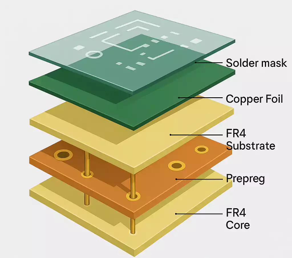
- Copper foil: The conductive layer that carries electrical signals.
- Base substrate (FR4 or others): The insulating and supporting layer that separates copper layers.
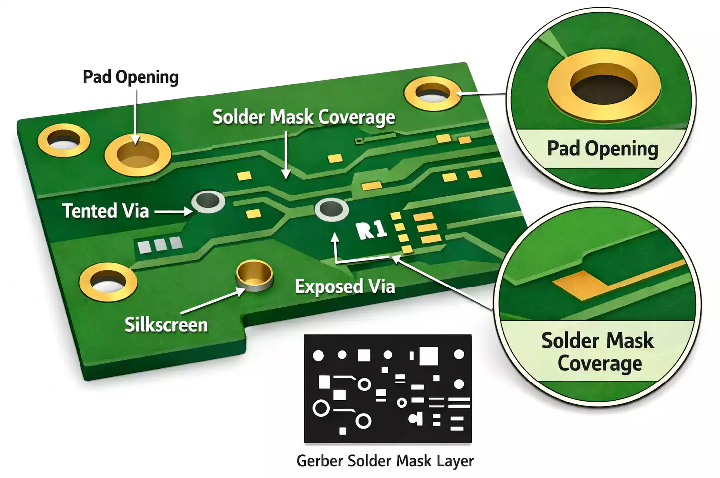
- Solder mask: A protective coating that prevents oxidation and short circuits.
- Silkscreen: Used to print labels, part numbers, and reference marks.
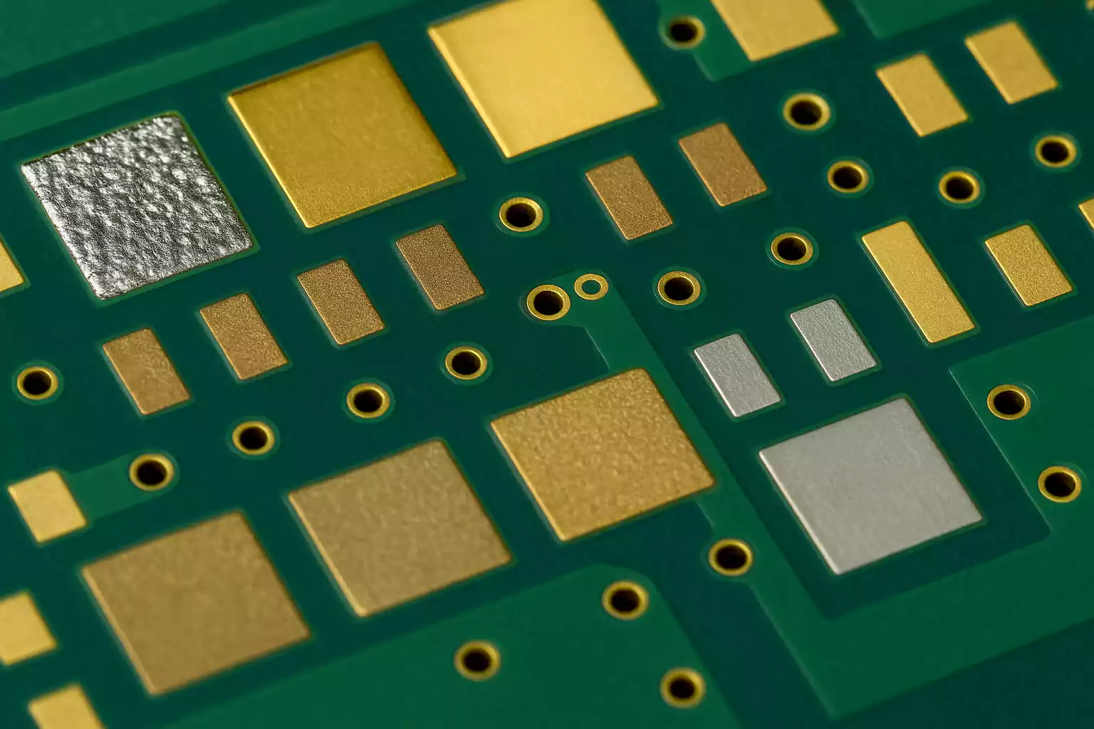
- Surface finish (ENIG, OSP, HASL, etc.): Keeps exposed copper pads solderable.
In most multilayer PCBs, the core and prepreg layers are made of FR-4, forming a sandwich structure with copper on both sides. That’s why “PCB FR4 material” and “FR4 PCB board” often refer to the same thing—the standard rigid laminate used in circuit fabrication.
Key Material Properties of FR4 PCB
While all FR4 laminates share a similar composition, their exact properties can vary depending on resin content, glass style, and manufacturing process. Below are the most important characteristics to consider when choosing a laminate.
1. Glass Transition Temperature (Tg)
Tg is the temperature at which the resin changes from rigid to soft.
- Standard FR-4: Tg ≈ 130–140 °C
- High Tg FR-4: Tg ≈ 170–200 °C
A higher Tg improves resistance to heat and repeated solder reflow cycles. For lead-free processes or boards with multiple reflows, always go with high-Tg FR4.
2. Dielectric Constant (Dk) and Loss Factor (Df)
These values describe how the material behaves at high frequencies:
- Typical Dk: 3.8–4.8
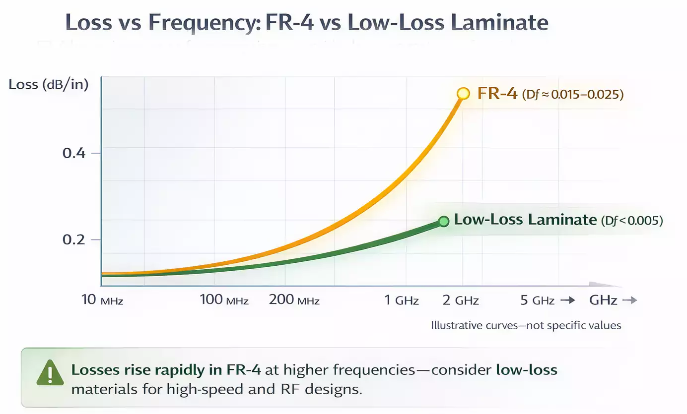
- Typical Df: 0.015–0.025
FR4 is fine for low- to mid-frequency designs. For RF or high-speed digital circuits, use PTFE or hydrocarbon laminates, as FR4's losses become noticeable at higher frequencies.
3. Board and Copper Thickness
- Common board thickness: 1.6 mm, 1.0 mm, 0.8 mm
- Common copper weights: 0.5 oz, 1 oz, 2 oz per ft²
Thicker copper handles higher current and improves heat spreading, but makes etching and fine traces harder. Standard 1 oz copper with 1.6 mm FR4 suits most 4- and 6-layer designs.
4. Thermal Conductivity
FR4 has a low thermal conductivity (~0.3 W/m·K).
That’s sufficient for low-power devices, but not for high-power LEDs or power converters. In those cases, aluminum or metal-core PCBs are better choices.
5. Flame Retardance and Strength
FR4 meets UL94V-0 fire-safety requirements and offers excellent mechanical rigidity.
It maintains dimensional stability even under moderate mechanical and thermal stress.
Quick Reference: Common FR-4 Specs
| Glass transition (Tg) | 130–200 °C | Heat resistance, reflow durability |
| Dielectric constant (Dk) | 3.8–4.8 | Signal speed, impedance |
| Dissipation factor (Df) | 0.015–0.025 | High-frequency loss |
| Thermal conductivity | ~0.3 W/m·K | Heat dissipation |
| Water absorption | ≤ 0.15% | Stability in humid environments |
| Flame rating | UL94 V-0 | Safety standard compliance |
When FR4 PCB Is the Right Choice—and When It Isn’t
✅ Use FR4 when:
- Your design runs at moderate speeds or frequencies (digital, analog, control circuits).
- You need multilayer flexibility (up to ~10 layers).
- Cost and availability matter most.
- The operating temperature stays below 130–150 °C.
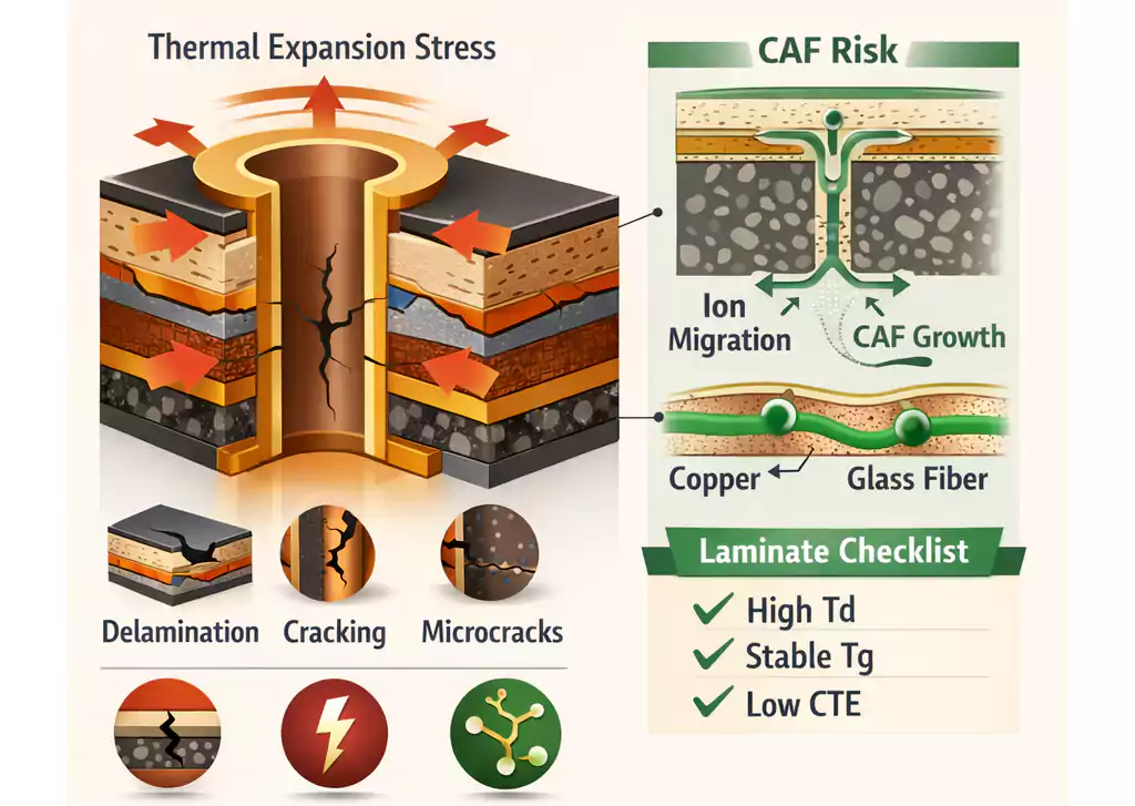
⚠️ Avoid or upgrade when:
- Your design involves RF or high-speed (GHz-range) signals.
FR4’s Df is too high for controlled impedance lines over long distances. - You need efficient heat dissipation, such as LED lighting or power modules.
FR4 traps heat; aluminum or IMS boards conduct it away. - You’re dealing with extreme temperature cycles (in automotive or aerospace applications).
In that case, high-Tg or ceramic materials handle stress better.
FR4 vs. Other PCB Materials
FR-4 vs. Aluminum PCB (IMS)
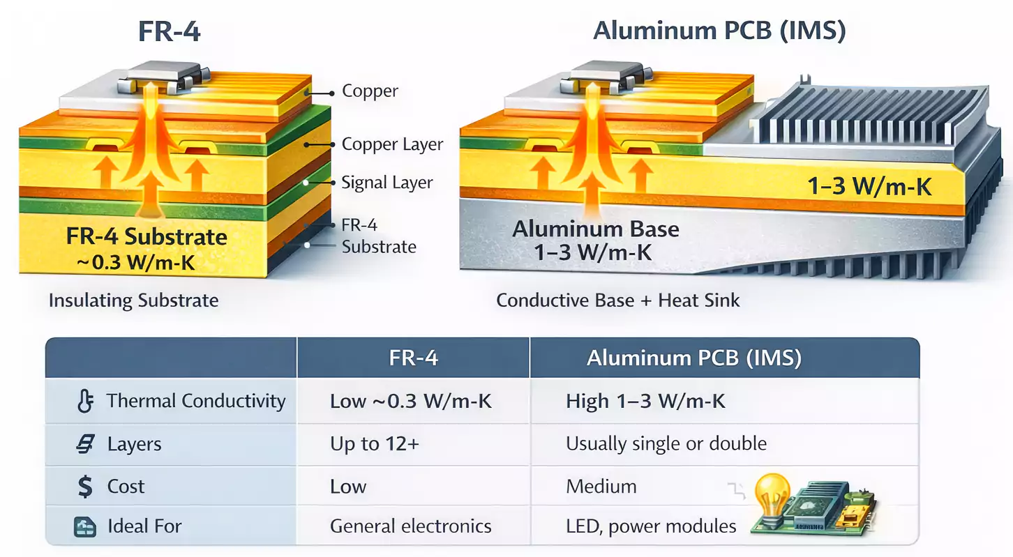
| Thermal conductivity | Low (~0.3 W/m·K) | High (1–3 W/m·K) |
| Layers | Up to 12+ | Usually single or double |
| Cost | Low | Medium |
| Weight | Light | Heavier |
| Ideal for | General electronics | LED, power, thermal designs |
Aluminum PCBs provide excellent heat transfer and stability. FR4 PCB is dominant for cooler signal and logic circuits.
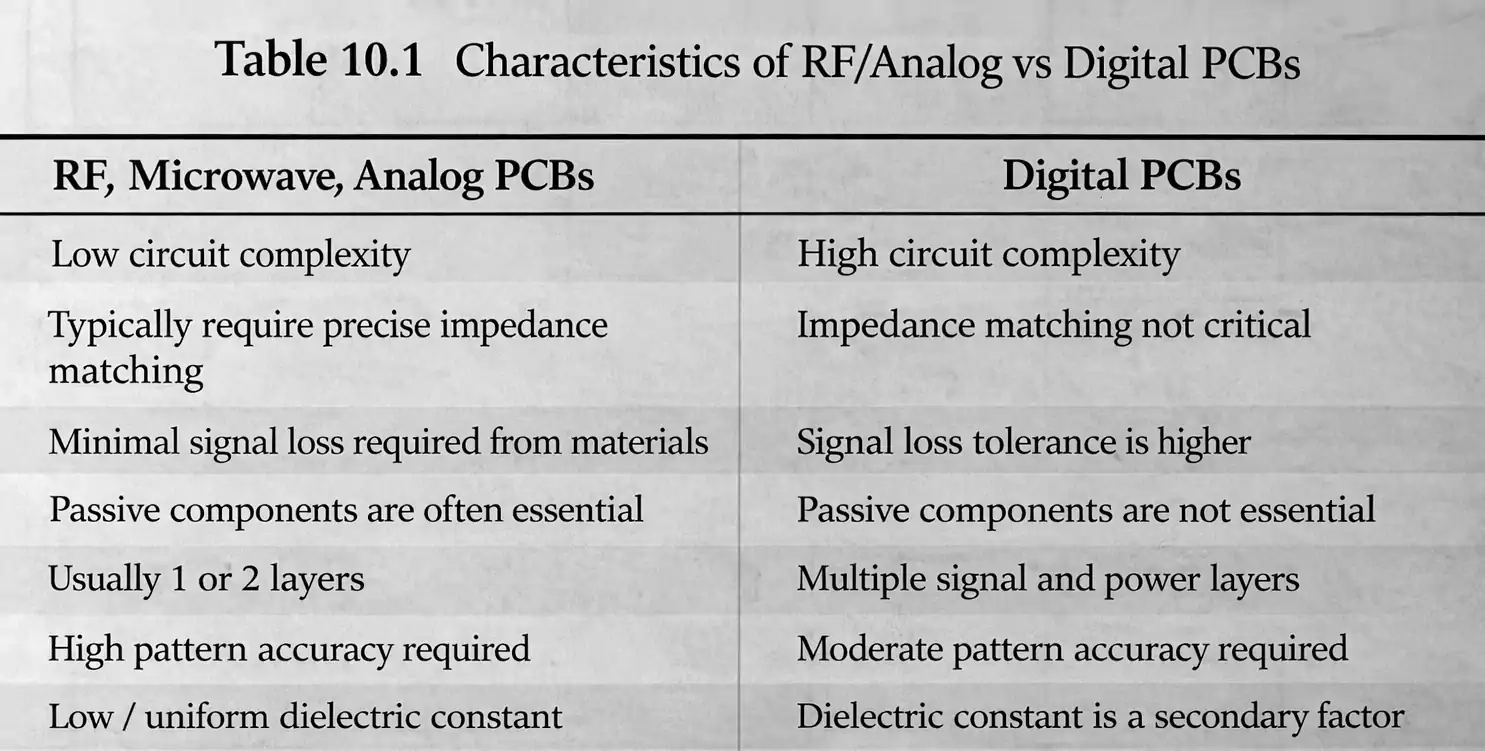
FR-4 vs. High-Frequency Materials (PTFE, Rogers, etc.)
| Dielectric constant (Dk) | 3.8–4.8 | 2.2–3.2 |
| Loss factor (Df) | 0.015–0.025 | < 0.005 |
| Process compatibility | Easy | More demanding |
| Cost | Low | High |
| Ideal for | General digital, analog | RF, microwave, 5G, radar |
If your design operates at GHz frequencies or requires precise impedance control, upgrading to a low-loss laminate is worth it. For most other designs, FR4 remains a cost-effective and practical default.
How to Choose the Right FR-4 Thickness and Stack-Up
A PCB’s thickness and copper weight directly affect impedance, strength, and fit with connectors or enclosures.
Common recommendations
- 1.6 mm thick, 1 oz copper – Standard for most 4- and 6-layer boards.
- 1.0 mm or 0.8 mm – For compact modules or weight-sensitive products.
- 2 oz copper – For higher current or thermal performance (check trace widths).
Your manufacturer can help you select from standard core and prepreg combinations that achieve your target impedance. When in doubt, share your stack-up goals—signal layers, power/ground planes, and expected dielectric thickness—and they’ll suggest the best match.
FAQ About FR4 PCB
Q: What does FR-4 mean in PCB?
A: FR-4 refers to a fiberglass-epoxy laminate with flame-retardant properties, used as the main insulating substrate in most PCBs.
Q: What are PCB boards made of?
A: PCB boards are made of copper layers, FR-4 substrate, solder mask, silkscreen, and surface finish.
Q: Is FR-4 good for high-frequency designs?
A: It’s fine for low- to mid-frequency signals, but at higher frequencies (above a few GHz), losses increase noticeably.
Q: What is the standard FR-4 thickness?
A: 1.6 mm is the most common; 1.0 mm and 0.8 mm are also popular for compact designs.
Q: When should I choose an aluminum PCB instead of FR-4?
A: Use aluminum PCBs when thermal management is critical, such as in LED lighting or power converters.
Conclusion
FR4 PCB delivers a proven balance of strength, insulation, and manufacturability for everyday electronics.
Yet as designs reach GHz speeds or operate in high-power domains, their limits become clear.
Evaluate your application early—selecting the right substrate is the easiest way to ensure electrical integrity and long-term reliability.