In modern SMT (Surface Mount Technology) production, product defects don't only result from poor solder joints—they can also arise from wrong component placement, reversed polarity, or incorrect part values. This is where In-Circuit Testing (ICT) becomes essential.
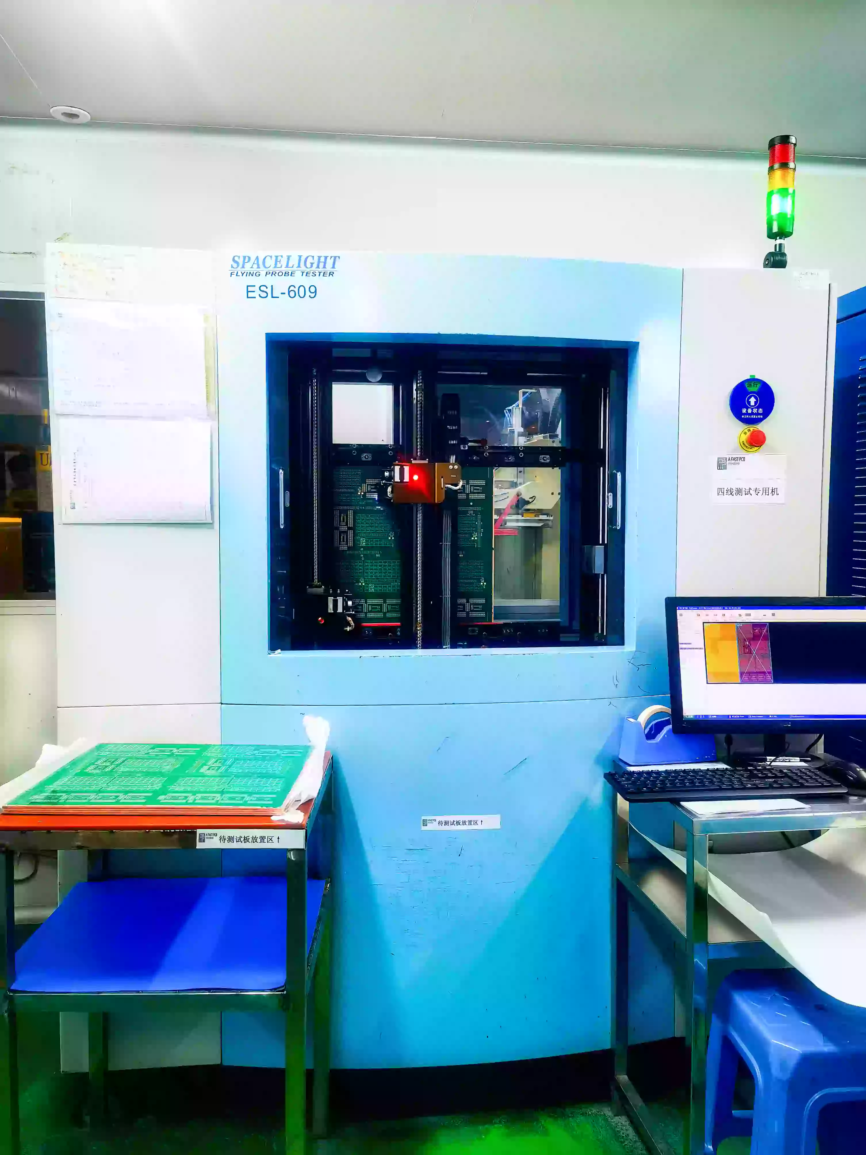
Flying Probe Testing (FPT) is a type of ICT that uses moving probes instead of a fixed test fixture. It's widely used for prototypes, new product introduction (NPI), and low-volume PCB assembly, offering fast setup and high test coverage without the need for a custom test jig.
How Does Flying Probe Testing Work?
Flying probe testers use 4 to 8 high-speed probes mounted on X-Y moving arms. These probes are guided by software to contact specific test pads and vias on the PCB. Once in contact, they measure:
Resistance (for resistors)
Capacitance (for capacitors)
Inductance (for inductors)
Component polarity
Shorts and open circuits
Only one component is tested at a time, while others are electronically isolated to ensure accurate results.
Key Advantages of Flying Probe Testing
No Fixture Needed
Skip the time and cost of building a bed-of-nails fixture. Just upload your CAD files and start testing within hours.
Low Cost
Ideal for small runs, prototypes, or frequent design changes. You only pay for the programming—not hardware.
High Accuracy
With ±10 μm repeatability and tiny contact points, FPT can detect faults in PCB areas too small for traditional ICT.
Flexible & Easy to Operate
Setup is quick and doesn't require advanced technical skills—great for fast-paced production lines.
Non-Destructive Electrical Testing
Tests key parameters like resistance, capacitance, shorts, opens, and even pin polarity without applying full power.
Limitations of Flying Probe Testing
While flying probe testers are powerful, they aren't perfect:
Slower Than Bed-of-Nails
Each probe moves individually, so test time is longer—especially for complex boards.
Not Ideal for High-Volume Production
Needle-based ICT can test thousands of nodes in one contact; FPT tests one at a time.
Possible Cosmetic Issues
Probes leave small marks on solder pads, which may be unacceptable for high-aesthetic products.
Limited Dual-Side Testing
FPT typically tests one side at a time, requiring manual flipping of the PCB.
May Miss Some Solder Defects
If a test pad is missing, the probe might touch a component lead directly—making it harder to detect lifted leads.
Maintenance Best Practices for Flying Probe Testers
To keep your FPT system running reliably:
Daily Cleaning
Use vacuum cleaners and alcohol for dust removal—never compressed air.
Air Filter Checks
Inspect for oil or moisture. Replace filters if discolored or wet.
Self-Diagnostics
Run the SELFTEST feature (e.g., in VIVA software) to check system health.
Probe Calibration
Regularly inspect probes and replace worn ones. Always calibrate afterward.
Watch for Oil Leaks
Oil marks on the Y-axis usually mean filter failure—stop the machine and inspect.
Computer Security
Keep backups, avoid installing unrelated software, and scan all external drives for viruses.
When to Use Flying Probe Testing
| Use Case | Flying Probe Testing | Bed-of-Nails ICT |
|---|---|---|
| Prototypes & NPI | ✅ Ideal | ❌ Too slow & costly |
| Low-Volume Production | ✅ Cost-effective | ❌ Fixture not worth it |
| High-Volume Production | ❌ Too slow | ✅ Very efficient |
| High Pin Density PCBs | ✅ Excellent precision | ❌ Limited by probe size |
| Time-to-Market Needs | ✅ Fast setup (no fixture) | ❌ Fixture delays |
FAQ: Flying Probe Testing
When should I choose Flying Probe Testing over ICT?
FPT is ideal for prototypes and low to mid-volume production. It requires no fixture, supports quick program setup, and suits frequent design changes—unlike ICT, which is better for mass production due to higher upfront costs.
How should I design test points for FPT?
Use exposed, round copper pads ≥0.5 mm, with ≥0.75 mm spacing. Avoid placing test points on small SMD pins or near solder joints. Keep test access clear of dense or sensitive areas.
What can FPT systems detect?
Opens, shorts, resistance, capacitance, inductance, polarity, phase shift, and micro-shorts. Some systems include cameras for component orientation and polarity checks.
What data is needed for FPT programming?
CAD files (ODB++, IPC-2581), BOM, and XY coordinates. Ensure all files match the latest PCB revision to avoid test mismatches.
What are FPT’s limitations?
Slower than ICT and limited in dense or multilayer boards. To reduce false calls, use fiducials, maintain test point quality, and avoid probing on unstable pads.
Final Thoughts
Flying Probe Testing is a smart solution for electronics manufacturers who need fast, flexible, and accurate PCB testing without the hassle of fixtures. While it’s not the best fit for high-volume production, it shines in early-stage development, small batches, and precision-critical applications.

If you’re working with rapid-turn prototypes or diverse product lines, adopting FPT in your test strategy can save time, cut costs, and catch issues early—ensuring smoother production and higher product quality.