


Introduction
Printed Circuit Boards (PCBs) are the backbone of virtually every modern electronic device, from smartphones and laptops to industrial control systems. However, even the most well-designed PCB can suffer from a short circuit — a condition where unintended electrical connections allow current to flow along the wrong path. This fault can be as subtle as a microscopic solder bridge or as severe as an internal copper trace breakdown.
A PCB short circuit can have serious consequences. At best, it may cause unstable device behavior, such as intermittent resets or erratic sensor readings. At worst, it can lead to excessive heat generation, burned components, or complete system failure. In high-power applications, shorts can even cause catastrophic damage to other connected devices or pose a fire risk.
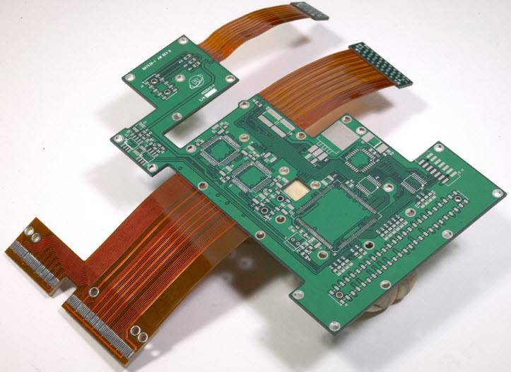
In manufacturing and repair environments, speed is critical. The longer a short circuit remains undiagnosed, the more time, labor, and cost it takes to restore functionality. This is especially true in multilayer PCBs, where faults can hide inside inner layers and are difficult to detect without proper tools and techniques.
Understanding the causes, detection methods, and repair options for PCB short circuits is essential for electronics engineers, technicians, and hobbyists alike. This guide will walk you through:
- Common causes of PCB shorts, including soldering mistakes and design flaws
- Diagnostic techniques using tools like multimeters and thermal imaging cameras
- Practical repair methods for restoring a faulty PCB
- Preventive measures to avoid short circuits in future designs
By the end of this guide, you’ll have a systematic approach to diagnose, fix, and prevent PCB short circuits, improving both product reliability and repair efficiency.
Common Causes of PCB Short Circuits
Before you can fix a PCB short circuit, you need to understand why it happened. In electronics troubleshooting, correctly identifying the cause is half the battle. While PCB shorts can occur at any stage — from design to assembly to field use — most issues fall into a few common categories.
Solder Bridges
A solder bridge occurs when excess solder unintentionally connects two or more conductive pads or traces. This often happens when:
- Too much solder paste is applied before reflow
- Manual soldering uses an oversized tip or poor technique
- Surface-mount components (especially fine-pitch ICs) are not aligned correctly
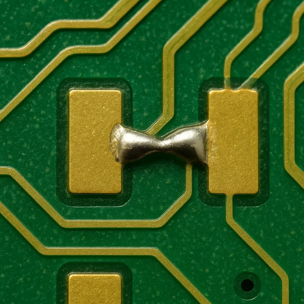
Solder bridges are one of the most frequent short circuit culprits in SMT assembly. Under a microscope, they appear as shiny blobs connecting adjacent pins.
Prevention tip: Use solder masks, maintain proper stencil thickness, and verify reflow profiles to reduce the risk of bridging.
Component Misplacement
Installing a component in the wrong orientation or on the wrong pads can short its leads. For example:
- Reversing a polarized capacitor so its terminals connect to unintended nets
- Misaligning a connector so pins overlap multiple signal traces
- Using a wrong-footprint part where pads touch unintentionally
Even experienced assemblers can make this mistake when dealing with high-density boards or poorly marked silkscreens.
Damaged or Degraded PCB Layers
Over time or due to manufacturing defects, copper traces or vias can become damaged:
- Mechanical stress can crack traces and force copper into contact with nearby lines
- Delamination or moisture ingress can reduce insulation resistance between layers
- Overheating can burn through dielectric materials
This type of short is more common in multilayer PCBs and can be difficult to detect without specialized testing.
Design Errors
Sometimes, the short circuit isn’t due to a mistake in manufacturing — it’s in the design. Common examples include:
- Routing traces too close together without meeting IPC spacing standards
- Forgetting to add a solder mask dam between fine-pitch pads
- Unintentionally connecting planes in CAD due to incorrect net assignments
Preventive design rule checks (DRCs) in PCB layout software can catch these before production.
Foreign Conductive Debris
Small particles of solder, copper, or even dust contaminated with flux residues can create a conductive path between traces. This is especially problematic in rework environments where multiple boards are being soldered in close proximity.
Conductive debris shorts often cause intermittent faults — the short appears only when the debris shifts into contact or under certain humidity conditions.
In summary: Most PCB short circuits are preventable with careful design, controlled assembly processes, and thorough inspection. However, even with best practices, occasional defects still occur — which is where diagnostic tools come in, as we’ll cover next.
Tools and Equipment for Troubleshooting PCB Shorts
Diagnosing a PCB short circuit efficiently depends on having the right tools. While experience plays a big role, using specialized equipment can drastically reduce the time spent locating and fixing the fault. Below are the most useful tools for PCB short detection and repair.
Multimeter
A digital multimeter (DMM) is the most essential tool for PCB troubleshooting. In continuity or resistance mode, it can help:
- Identify direct shorts between power and ground planes
- Measure resistance to pinpoint the lowest-resistance path to the fault
- Check component pins for unintended connections
Tip: For sensitive circuits, use a DMM with a low test voltage in continuity mode to avoid damaging delicate components.
Thermal Imaging Camera
When a PCB is powered, a short circuit often generates localized heat. A thermal camera (infrared imaging) allows you to:
- Spot “hot spots” where excessive current is flowing
- Identify the exact component or trace causing the fault
- Work safely without physically touching the board during testing
Affordable smartphone-compatible thermal cameras are now available, making this method more accessible to hobbyists and small repair shops.
Bench Power Supply with Current Limiting
A laboratory power supply lets you safely inject power into the PCB:
- Use a low voltage (e.g., 1–2 V) and set a current limit to prevent damage
- Observe current draw — high current indicates a short
- Combine with a thermal camera or touch test (with caution) to locate the fault area
This is especially useful for low-resistance shorts between power rails.
Microscope or Magnifying Glass
High-magnification inspection tools help detect:
- Solder bridges between fine-pitch IC pins
- Cracked or lifted pads making unintended contact
- Foreign conductive particles lodged between traces
A stereo microscope is ideal for precise visual inspection, especially for surface-mount technology (SMT) boards.
Tone Generator or Short Locator Tools
Specialized short locator devices inject an AC signal into the PCB. By using a sensitive magnetic probe, you can trace the path of current flow toward the short. This technique is particularly useful for multilayer PCBs, where visual inspection alone may not be enough.
Pro Tip: For the fastest results, many repair technicians combine methods — starting with a multimeter to confirm a short, then using a bench power supply plus a thermal camera to pinpoint it.
Step-by-Step Diagnosis Techniques
Finding a PCB short circuit is like detective work — you gather clues, narrow down suspects, and confirm the culprit. The key is to proceed methodically, using the right combination of inspection and measurement. Here’s a proven step-by-step process.
Visual Inspection
Before touching any instruments, start with a careful visual check:
- Look for solder bridges between component leads, especially on fine-pitch ICs.
- Check for foreign debris like solder balls, copper shavings, or stray wire strands.
- Inspect for burn marks or discoloration that indicate overheating.
Tools: Magnifying glass or microscope.
Tip: Tilt the PCB under strong light to make tiny solder bridges easier to spot.
Continuity and Resistance Tests with a Multimeter
A multimeter is your first electronic detective tool:
- Set the meter to continuity mode (beep mode) or low-resistance mode.
- Probe between VCC and GND to confirm if a short exists.
- If continuity beeps or resistance is near zero, there’s a short somewhere on the power rail.
- Divide and conquer: Disconnect sections of the board (remove jumpers, desolder certain components) to isolate the fault area.
Advanced tip: Measure resistance from multiple test points — the closer to the short, the lower the resistance reading will be.
Using a Thermal Camera to Find Hot Spots
If the board can be powered safely:
- Connect it to a bench power supply set to a low voltage (1–2 V) with a current limit.
- Turn on the supply — the shorted area will heat up quickly.
- Scan the PCB with a thermal imaging camera to locate the warmest spot.
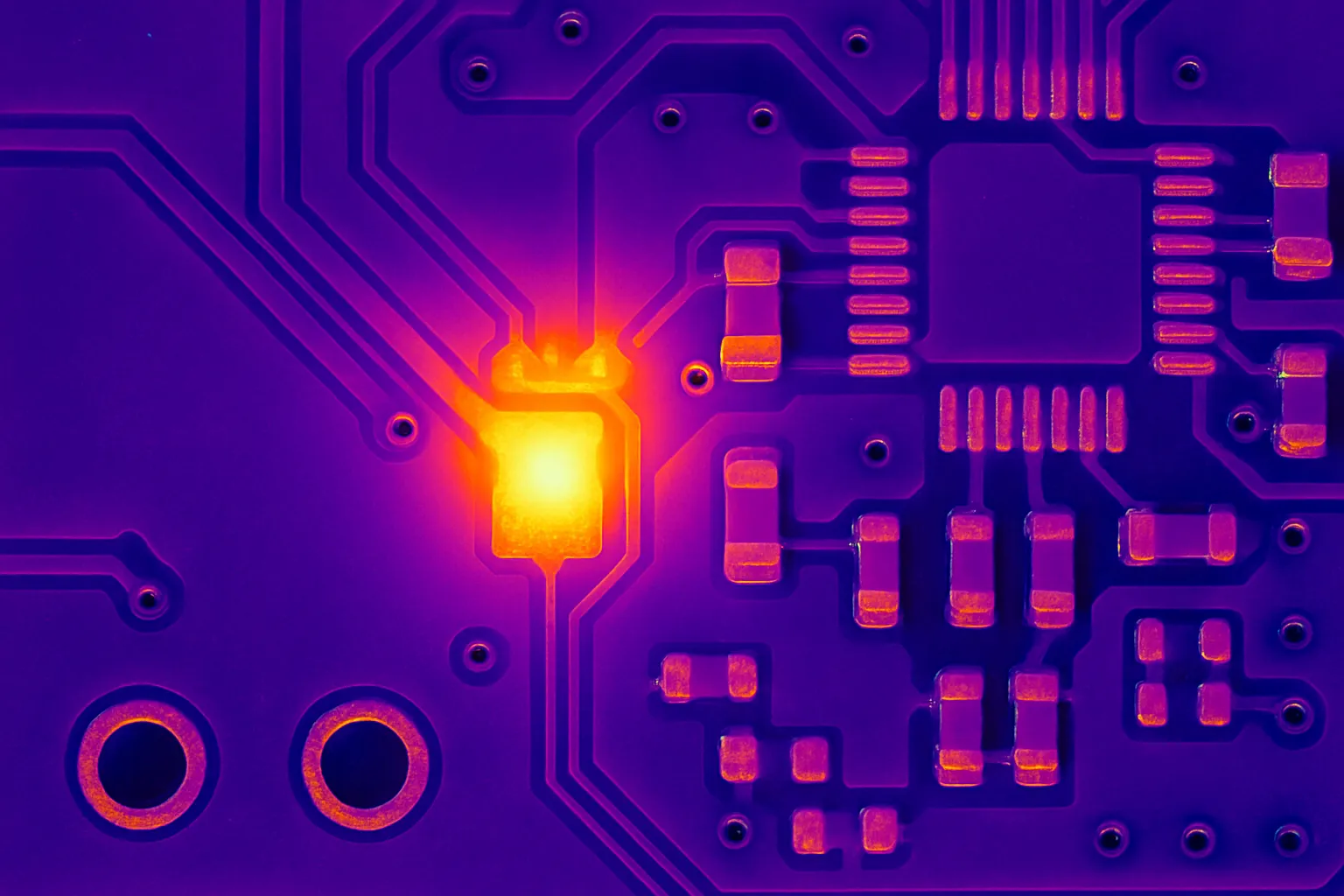
This is particularly effective for internal shorts in multilayer boards where visual inspection fails.
Current Injection Method
When a thermal camera isn’t available, you can still locate shorts by injecting current:
- Use a low-voltage, current-limited bench supply.
- Power the board’s affected rail directly.
- Feel the board with your fingertip (caution — touch only briefly to avoid burns) or use a temperature probe to detect heating.
This low-voltage method minimizes further damage while still revealing the short location.
Layer Isolation in Multilayer PCB
For complex boards:
- Use the cut-trace method: sever suspect traces temporarily to isolate sections of the circuit.
- Test each section independently until the short is confined to a smaller region.
- For professional repair labs, X-ray inspection or time-domain reflectometry (TDR) can be used to find inner-layer faults without cutting traces.
Pro Workflow Example:
- Visual inspection under a microscope → remove obvious solder bridges.
- Multimeter continuity check between power rails.
- Divide and conquer by isolating PCB sections.
- Bench power supply with thermal imaging for final pinpointing.
Common Fixing Methods for PCB Shorts
Once you’ve identified the exact location of a PCB short circuit, the next step is to remove the fault and restore the board to working condition. The best repair method depends on the cause of the short, the board’s complexity, and the tools available.
Removing Solder Bridges
If the short is caused by excess solder connecting two pads:
- Use solder wick (desoldering braid) to absorb excess solder. Apply flux for better wicking performance.
- Alternatively, use a hot air rework station to reflow the solder and let surface tension separate the pads.
- For fine-pitch ICs, gently drag the soldering iron tip across the pins with added flux to “comb out” the bridge.
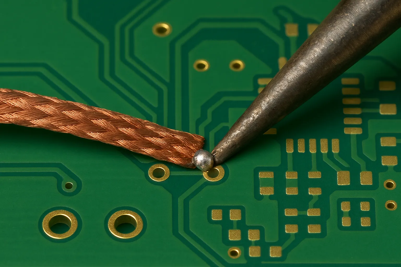
Tip: Always clean the area with isopropyl alcohol (IPA) afterward to remove flux residue.
Re-soldering or Replacing Faulty Components
If a component is damaged, misaligned, or internally shorted:
- Desolder it using hot air or a soldering iron with desolder pump.
- Replace it with a known-good component, ensuring correct orientation.
- Double-check surrounding pads for lifted copper or damage before reinstallation.
This is often the solution for shorted capacitors, MOSFETs, or ICs.
Cleaning Conductive Contaminants
Dust, metal filings, or solder balls can create intermittent shorts:
- Use compressed air to blow away debris.
- Brush the board with an ESD-safe brush dipped in IPA.
- For stubborn contamination, use an ultrasonic cleaner with PCB-safe solution.
Repairing Damaged Traces or Pads
When the short occurs due to physical damage:
- Cut the faulty trace with a precision knife to break the short.
- Reroute the signal with insulated jumper wire or adhesive copper tape.
- Secure and insulate the repair with conformal coating.
Internal Short Repairs (Advanced)
For shorts inside multilayer PCBs:
- Identify the faulty layer using thermal imaging or TDR.
- Carefully mill away a section of the PCB to expose the trace.
- Isolate or cut the trace, then reroute with jumper wiring.
This method is complex, time-consuming, and best suited for high-value boards where replacement is not an option.
Repair Reminder: After fixing the short, always re-test
- Perform a continuity check to confirm the short is gone.
- Power up gradually using a current-limited supply.
- Run functional tests to ensure the circuit works as intended.
Preventive Measures in Design and Assembly
While repairing PCB short circuits is important, preventing them is far more efficient. By implementing good design practices, careful assembly processes, and thorough quality checks, you can greatly reduce the likelihood of shorts in both prototypes and production runs.
Design StageMany shorts originate in the PCB layout phase, long before a physical board is built. To prevent them:
- Maintain adequate clearance: Follow IPC-2221 or IPC-7351 standards for minimum trace spacing based on operating voltage.
- Use solder mask dams between fine-pitch pads to prevent solder bridging during reflow.
- Run Design Rule Checks (DRC) in your PCB CAD software to catch unintentional net connections.
- Add test points on critical power rails to speed up troubleshooting if a short occurs.
Assembly Stage
Even a flawless design can fail if the assembly process introduces defects:
- Apply the correct solder paste volume by selecting proper stencil thickness.
- Keep components aligned during placement — especially fine-pitch ICs and connectors.
- Follow the correct reflow profile to avoid solder splatter or incomplete melting.
- Use anti-static handling procedures to prevent electrostatic discharge damage that can cause internal shorts in ICs.
Inspection and Testing
Quality control is the last defense before a board leaves the factory:
- Automated Optical Inspection (AOI) detects solder bridges, misalignments, and debris.
- In-Circuit Testing (ICT) can catch shorts between power and ground nets before powering the board.
- Functional Testing (FCT) ensures the PCB operates correctly under load.
- For high-reliability products, consider X-ray inspection to check hidden solder joints on BGAs and multilayer boards.
Pro Tip: Build preventive checks into every stage of your workflow — design, assembly, and inspection. This way, potential shorts are caught early when they are easiest and cheapest to fix.
Conclusion
PCB short circuits are one of the most common — and potentially damaging — faults in electronic systems. They can result from solder bridges, design oversights, damaged PCB layers, or foreign conductive debris, and they can range from minor nuisances to catastrophic failures.
By following a structured troubleshooting workflow — starting with visual inspection, confirming with a multimeter, and using advanced tools like thermal cameras and current-limited bench supplies — you can quickly locate and fix most shorts.
Equally important is prevention. Applying best practices in PCB design, maintaining tight control over the assembly process, and implementing thorough inspection protocols will significantly reduce the likelihood of shorts ever occurring.
In short:
- Detect quickly to minimize damage and downtime
- Repair methodically to restore reliability
- Design and assemble carefully to avoid repeat issues
Whether you’re an electronics engineer, repair technician, or hobbyist, mastering PCB short circuit diagnosis and prevention will improve product quality, reduce repair costs, and ensure the long-term performance of your devices.