In today’s high-speed digital and RF systems, the printed circuit board (PCB) is far more than just a mechanical support for components.
As signal rates climb into the multi-gigabit-per-second (Gbps) range, the electrical properties of the PCB laminate directly determine whether signals stay clean, synchronized, and distortion-free.
This article breaks down the two most critical parameters for high-frequency and high-speed design — the dielectric constant (Dk) and the dissipation factor (Df) — and explains how they affect signal velocity, loss, and overall reliability. You’ll also learn why low-Dk, low-Df materials have become essential for modern high-speed circuits.
Why Electrical Performance Matters in High-Speed PCB Design
In low-speed electronics, a PCB mainly serves as a mechanical frame and wiring platform. But when edge rates reach the picosecond domain, the board becomes part of the transmission channel itself.
The laminate material now controls electromagnetic wave propagation — influencing delay, impedance, crosstalk, and attenuation.
Common applications where laminate properties are critical:
- High-speed serial interfaces (PCIe, USB 4.0, SATA, SerDes)
- Data-center and AI computing backplanes
- 5G and microwave RF modules
- Aerospace, radar, and defense electronics
Neglecting the dielectric characteristics in these systems can lead to signal degradation, jitter, and timing errors that no amount of post-layout tweaking can fix.
Dielectric Constant (Dk): The Parameter That Defines Signal Velocity
What Dk Means
The dielectric constant, also called relative permittivity, describes how much electric energy a material can store in an electric field.
Formally:
Dk = Capacitance with dielectric / Capacitance in air.
A higher Dk means greater energy storage capability but slower signal propagation.
How Dk Affects Signal Speed
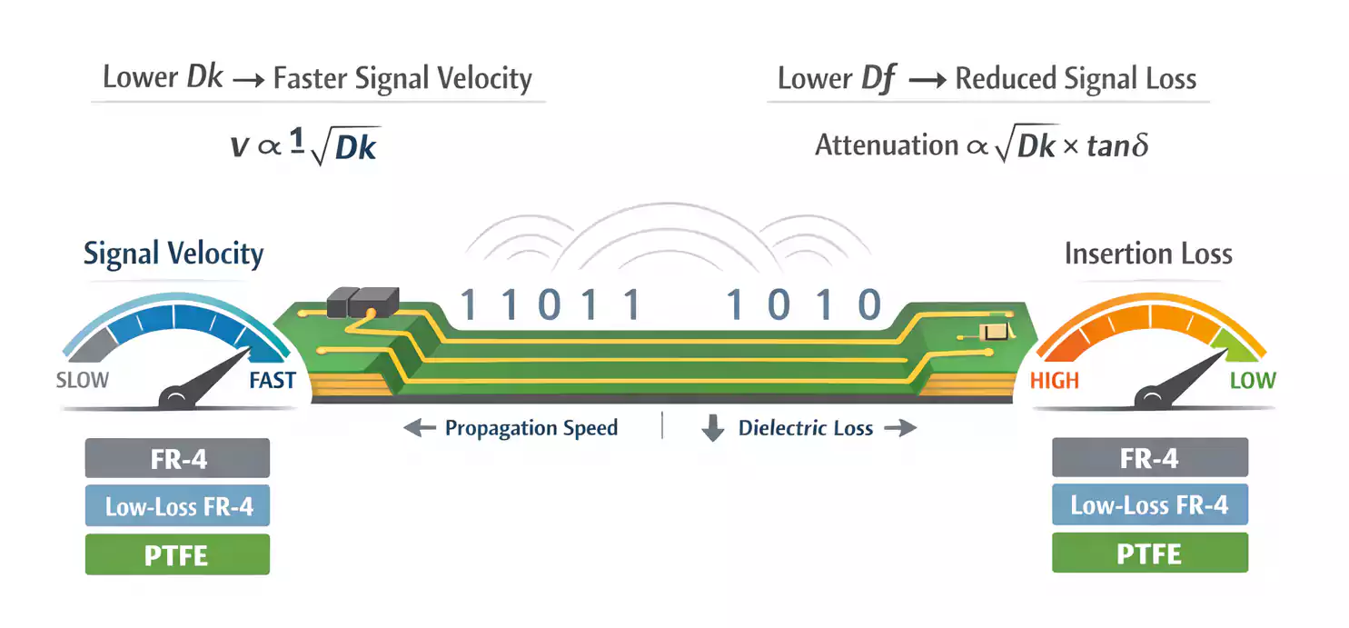
Signal velocity through a dielectric is inversely proportional to the square root of Dk:
v ∝ 1 / √Dk
So:
- Lower Dk → faster propagation, shorter delay
- Higher Dk → slower propagation, more timing skew
For reference:
- Air: Dk ≈ 1
- Standard FR-4: Dk ≈ 4.2–4.5
- Rogers 4350B: Dk ≈ 3.48
That reduction can cut propagation delay by 15–20%, a major improvement for multi-gigabit signals.
Dissipation Factor (Df): The Measure of Energy Loss
What Df Represents
The dissipation factor (Df), also called the loss tangent (tan δ), is the ratio of the energy lost in the dielectric to the total energy applied.
In simpler terms, Df indicates how much of your signal’s energy turns into heat as it travels through the PCB.
Why Df Matters
As frequency rises, molecular polarization can’t keep up, and dielectric loss increases.
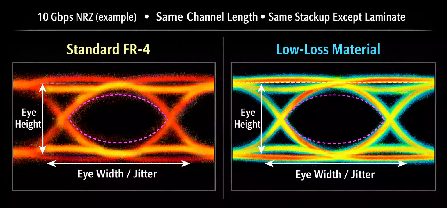
High-Df materials cause:
- Greater signal attenuation
- Reduced high-frequency amplitude
- Closed or distorted eye diagrams
Typical values:
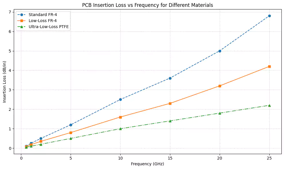
- Standard FR-4: Df ≈ 0.020
- Low-loss FR-4 (e.g., MEGTRON 6): Df ≈ 0.005
- Ultra-low-loss PTFE (e.g., Rogers 3003): Df < 0.001
Lower Df means cleaner, more reliable signals at high speeds.
From Lumped Elements to Transmission Lines
At low frequencies, a PCB trace behaves like a simple RC circuit — a resistor and a capacitor in parallel.
But once the trace length becomes comparable to the signal’s rise-time distance, it must be treated as a transmission line.
In this regime, Dk determines:
- Signal delay (propagation velocity)
- Characteristic impedance
- Timing skew and reflection behavior
Non-uniform or high Dk materials can lead to reflections, impedance mismatch, and EMI issues.
For this reason, low-Dk, tightly controlled materials are critical for signal-integrity consistency.
Dielectric Loss vs. Frequency
Dielectric loss depends on both Dk and Df.
The relationship can be roughly expressed as:
Attenuation ∝ √Dk × tan δ
Loss increases linearly with frequency. At multi-GHz ranges:
- High-frequency components dissipate quickly as heat.
- Rise times slow down.
- Effective bandwidth shrinks
In multi-gigabit links (25 G, 56 G, 112 G PAM4), even a small Df difference can cause large changes in insertion loss and BER (bit-error rate).
Frequency and Environmental Stability
In real-world conditions, Dk and Df aren’t constant — they vary with:
- Frequency: polarization lag alters Dk and Df
- Temperature: higher temperature → lower Dk, higher Df
- Humidity: moisture absorption → higher Dk and greater loss
Large variations across operating frequency or environment lead to:
- Inconsistent signal velocity
- Impedance drift
- Increased jitter and timing errors
Therefore, premium high-speed laminates must not only offer low Dk and Df values but also maintain flat, stable performance across wide frequency and environmental ranges.
Conclusion: Material Properties Define System Performance
In high-speed design, the PCB substrate is not a passive element — it’s an active part of the signal channel.
- Dk governs signal speed and delay.
- Df determines energy loss and eye-diagram quality.
- Stability ensures predictable system behavior over time.
Selecting the right laminate — such as Rogers, Isola, or Panasonic MEGTRON — can enhance bandwidth, reduce jitter, and help meet strict eye-mask requirements.
In the era of gigabit and terahertz data, PCB materials have become as critical as the chips they connect.
The dielectric constant and dissipation factor truly define the performance ceiling of every high-speed system.