

When designing and manufacturing printed circuit boards (PCBs), understanding the electrical performance of base materials is essential. Two key parameters—dielectric constant (Dk or εr) and dissipation factor (Df or tan δ)—directly affect how signals travel through a circuit.
In high-frequency and high-speed applications, these properties determine signal integrity, impedance control, and overall board performance.
This article covers the meanings of dielectric constant and permittivity, why Dk and Df vary with frequency and material, and how to use them when choosing PCB laminates.
1. What is Dielectric Constant (Dk or εr)?
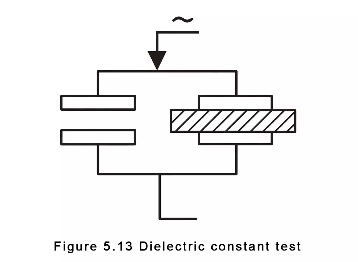
The dielectric constant, also called relative permittivity, measures how much electric energy a material can store compared to air or vacuum.
As Rogers Corporation explains, it’s the ratio of a capacitor’s capacitance with a dielectric to that with air.
A higher Dk allows a material to store more charge and shortens the wavelength. In RF and microwave circuits, this means smaller traces for a given frequency. However, higher Dk isn't always better—designers balance size, impedance, and loss.
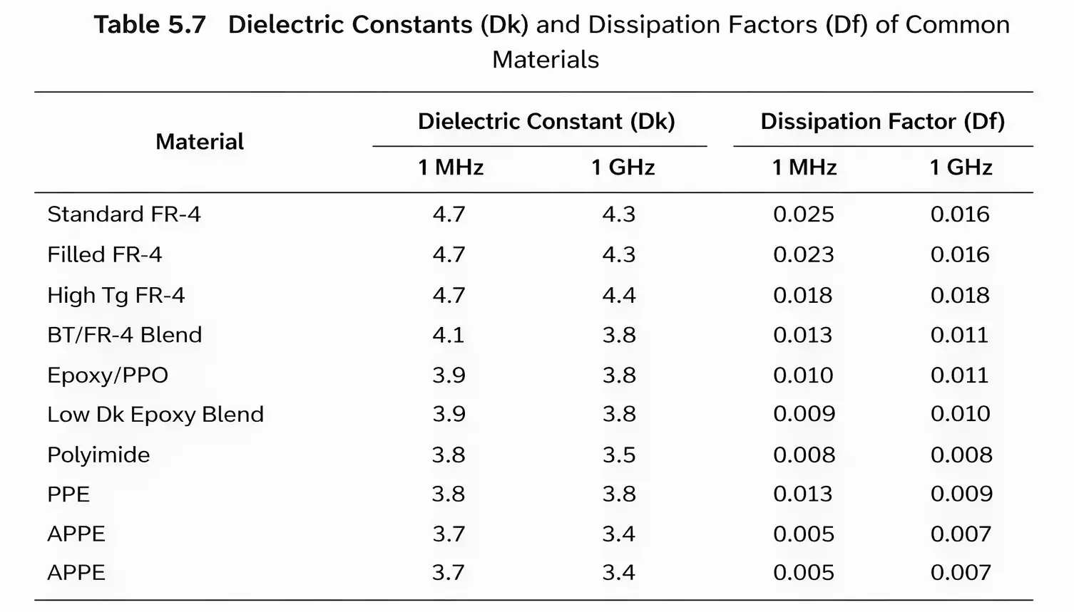
For example, the FR-4 dielectric constant is typically around 4.2 – 4.8 at 1 GHz, while the Teflon dielectric constant (PTFE) is much lower, about 2.1. That difference explains why PTFE-based laminates are widely used in high-frequency and low-loss RF boards.
2. Why Dk Is Not a Fixed Number
Dk changes with frequency
As Sierra Circuits notes, Dk is frequency-dependent. In most PCB materials, Dk decreases slightly with increasing frequency.
A laminate measured at 1 GHz might show Dk = 4.3, while the same material tested at 10 GHz could show Dk = 4.1. For high-frequency designs, engineers care more about Dk stability across a wide frequency range.
Dk depends on material composition
Many PCB cores are composites made of resin and fiberglass cloth. Each component has its own dielectric constant and dissipation factor.
When the resin-to-glass ratio changes, the overall Dk shifts toward whichever component dominates. Rogers' data shows that even a small change in resin content can alter Dk enough to affect impedance.
Dk can be anisotropic
Because PCB laminates contain woven glass-fiber layers, their dielectric properties are not uniform in all directions.
The Dk measured through the thickness (z-axis) may differ from that in the plane (x-y). Different test methods sense the electric field in different directions, so two “correct” Dk values can exist for the same material, depending on geometry.
3. Why Different Test Methods Give Different Dk/Df Values
Rogers and other material suppliers emphasize that the measurement method matters.
Different test setups, such as split-post resonators or clamped striplines, each produce unique electromagnetic fields.
One method might measure the z-axis response, another the x-y plane.
For example, a datasheet might report Dk = 3.48 @ 10 GHz (clamped stripline) and 3.66 @ 10 GHz (resonator).
Both are valid.
Engineering tip: When comparing materials, always specify both the test method and frequency. Without them, Dk and Df numbers are not directly comparable.
4. Using Data Tables to Show Frequency Effects
Isola Group provides an excellent example of how to illustrate frequency behavior.
Their data sheets list Dk and Df values at 100 MHz, 1 GHz, 2 GHz, and 10 GHz for the same laminate. They also show variations for glass style, resin content, and thickness.
Typical trends include:
- Dk decreases gradually with frequency.
- Df (loss tangent) increases slightly with frequency.
- Thicker or more resin-rich cores often have lower Dk and higher Df.
Charts in technical blogs make it easy to visualize how Dk and permittivity change with frequency, as seen in PCB handbooks.
5. What is Dissipation Factor (Df or tan δ)?
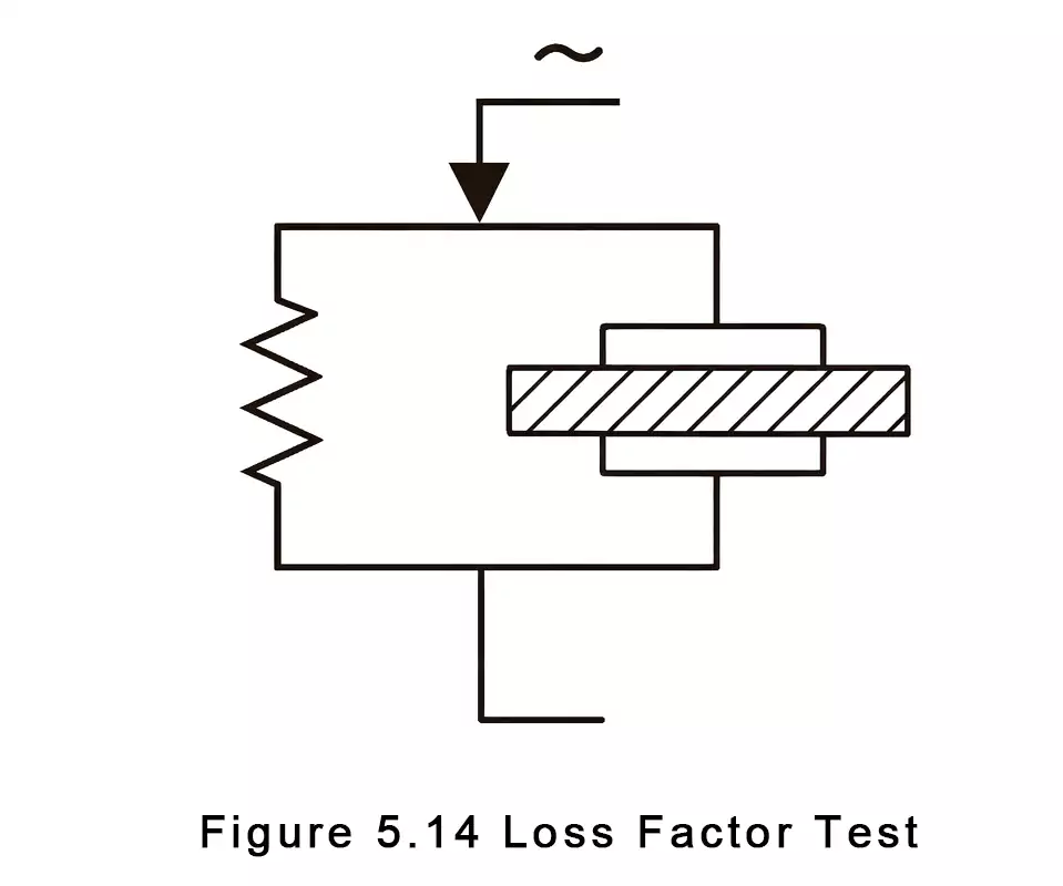
The dissipation factor (Df or tan δ) describes how much electromagnetic energy is converted into heat as a signal passes through the dielectric.
Altium defines Df as the ratio of dielectric power loss to stored electric field energy.
In simple terms:
- Low Df → less signal loss, better high-frequency performance.
- High Df → more energy lost as heat, faster signal attenuation.
6. Why Df Matters in High-Speed and High-Frequency Design
Df is one of the most critical parameters for today’s high-speed digital and RF boards.
According to Altium, the dissipation factor determines the dielectric loss component of total signal attenuation.
Even with minimal copper loss and reflection, high Df reduces maximum useful trace length due to signal decay.
That’s why high-speed materials such as Rogers 4000 series, Panasonic Megtron 6, and Isola I-Tera MT40 specify Df values as low as 0.003–0.005 @ 10 GHz—far below standard FR-4 (Df ≈ 0.02).
7. Df Also Varies with Frequency and Resin/Glass Ratio
Just like Dk, Df is not constant.
Industry data shows that Df usually increases with frequency and resin content, since resin causes greater loss than glass.
Designers working with fine-pitch or long-trace channels should always consider this effect during signal-integrity simulation.
Selecting materials with stable, low Df across the operating band is essential for 5G, automotive radar, and high-speed backplane applications.
Conclusion
Both dielectric constant (Dk) and dissipation factor (Df) are fundamental to PCB electrical performance.
Dk affects impedance, capacitance, and trace geometry, while Df defines how much signal energy is lost as heat.
Understand how dielectric constant and permittivity relate, compare values from the same test methods, and note how frequency and materials affect both—this will help you choose suitable laminates.
Whether you are working with FR-4 dielectric constant values or exploring Teflon dielectric constant for RF and microwave designs, selecting the proper material ensures controlled impedance and reliable performance at high frequencies.
