Selecting the right material is one of the most important decisions you will make in any custom PCB project. Materials don’t just determine how durable a board is—they influence signal integrity, heat dissipation, long-term reliability, manufacturability, and final production cost.
This guide breaks down the complex world of Custom PCB Material into a clear, practical reference you can use when choosing between FR-4, High-Tg, low-loss materials, and metal-core substrates.
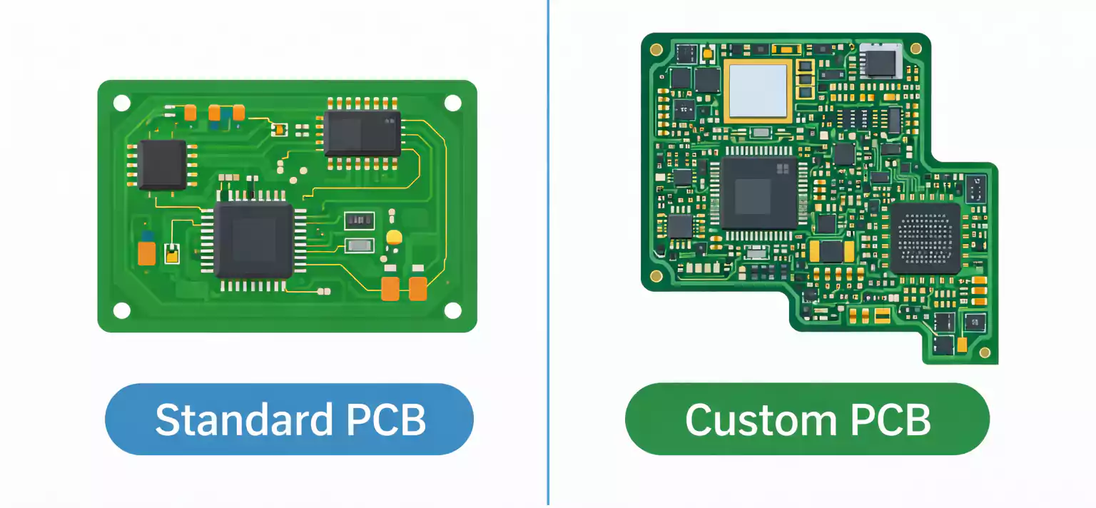
What Does “Custom PCB Material” Really Mean?
When engineers talk about “custom PCB materials,” they’re not referring to a single exotic laminate. Rather, they refer to a deliberately chosen material stackup intended to meet the electrical, thermal, environmental, and mechanical goals of a project.
A custom PCB material selection includes decisions about:
- Core material (laminate type)
- Prepreg (bonding layers)
- Copper foil type and weight
- Overall thickness and stackup
- Surface finish compatibility
- Thermal and mechanical constraints
- Signal integrity and impedance requirements.
Because different combinations of these materials can drastically change PCB behavior, “custom” means choosing the correct combination rather than relying on a generic default.
What Materials Make Up a PCB?
Before selecting materials, it helps to understand the three fundamental building blocks of any PCB.
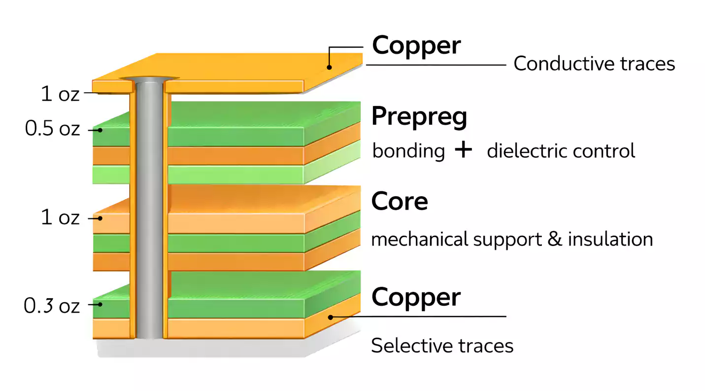
1. Prepreg
Prepreg is fiberglass cloth impregnated with resin but not fully cured. During lamination, prepreg melts and bonds the PCB layers together. Its resin content, thickness, and flow characteristics determine:
- Dielectric spacing
- Lamination strength
- Impedance control
- Structural stability
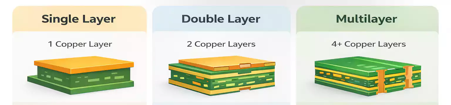
2. Core (Copper-Clad Laminate / CCL)
A core is a fully cured fiberglass-epoxy laminate clad with copper on both sides. It provides:
- The board’s base mechanical structure
- Electrical insulation
- Dimensional stability
Different core materials (FR-4, high-Tg FR-4, PTFE, ceramic-filled laminates, metal-core) serve different performance needs.
3. Copper Foil
Copper foil forms the conductive traces. Key considerations include:
- Copper weight (½ oz, 1 oz, 2 oz, etc.)
- Grain structure (affecting signal losses)
- Suitability for high-frequency applications
Together, prepreg, core, and copper determine the electrical and mechanical performance of your custom PCB.
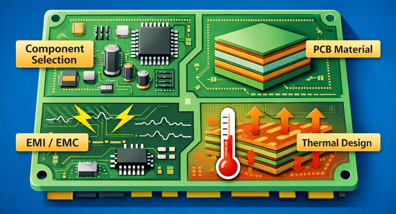
Why Material Selection Matters in Custom PCB Manufacturing
Choosing the right material impacts nearly every aspect of a PCB’s functionality and manufacturability.
1. Electrical Performance
Materials define:
- Signal speed
- Insertion loss
- Crosstalk
- Impedance stability
High-frequency designs especially depend on low-loss dielectrics.
2. Thermal Behavior
Poor thermal performance leads to:
- Delamination
- Pad lifting
- Cracked vias
- Reduced component life
High-Tg and metal-core materials improve thermal resilience.
3. Mechanical Stability
Material stability under heat and humidity affects:
- Dimensional accuracy
- Registration between layers
- Reliability under thermal cycling
4. Manufacturability
Some materials:
- Require longer lamination cycles.
- It's harder to drill
- Demand tighter process controls
- Have limited availability
This can affect both cost and lead time.
5. Total Cost of Ownership
A cheaper material may work for prototypes but ultimately fail in real-world operation. Conversely, a high-performance laminate may be unnecessarily expensive unless the application requires it.
The 6 Most Important PCB Material Properties
These are the properties engineers must consider when selecting Custom PCB Material.
1. Dielectric Constant (Dk)
Dk determines:
- Signal propagation speed
- Controlled impedance accuracy
Lower Dk materials support faster signals and tighter impedance control.
2. Dissipation Factor (Df)
Also known as the loss tangent, Df measures signal loss.
Low Df = lower attenuation = essential for high-speed or RF designs.
3. Glass Transition Temperature (Tg)
Tg indicates the temperature at which the laminate shifts from rigid to rubbery.
Higher Tg improves:
- Heat tolerance
- Dimensional stability
- Soldering survivability
4. Coefficient of Thermal Expansion (CTE)
CTE defines how much a material expands when heated.
Lower CTE means:
- Better via reliability
- Reduced risk of delamination
- Stronger mechanical stability
5. Thermal Conductivity
Critical for power electronics, LEDs, or heat-dense areas.
Metal-core materials dramatically outperform FR-4 in this category.
6. Moisture Absorption
High moisture absorption can degrade:
- Dielectric performance
- Dimensional accuracy
- Long-term reliability
PTFE and high-speed laminates typically outperform FR-4 in this regard.
The Four Major Types of Custom PCB Material
Instead of overwhelming readers with dozens of laminate names, we’ll focus on four categories that cover 95% of real-world needs.
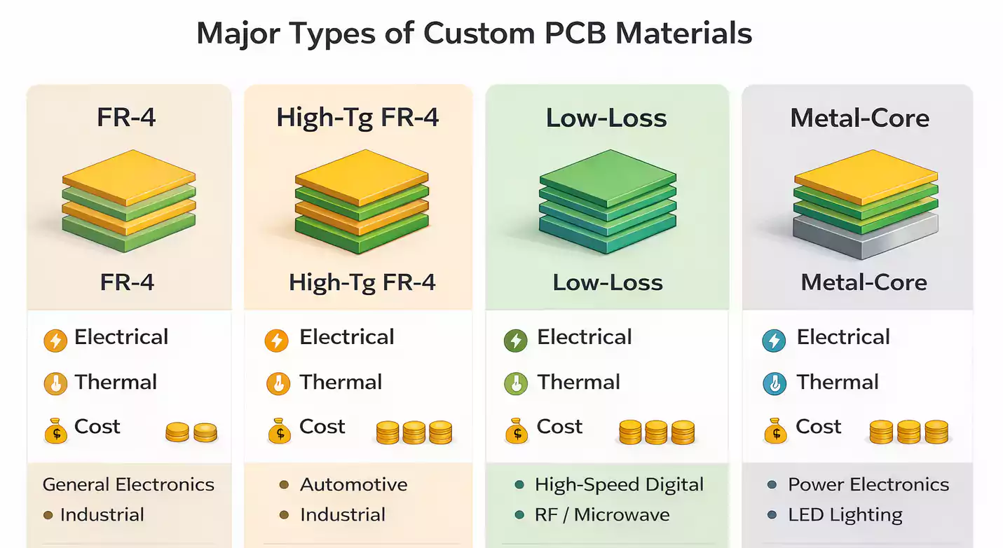
1. Standard FR-4
FR-4 is the most widely used PCB material—affordable, versatile, and compatible with nearly all manufacturing methods.
Best for:
- Consumer electronics
- Industrial controllers
- Cost-sensitive designs
- Low-to-moderate speed digital signals
Limitations:
- Higher dielectric loss
- Limited high-temperature performance
- Not ideal for RF or high-speed applications
2. High-Tg FR-4
High-Tg materials (170–180°C+) offer improved thermal stability over standard FR-4.
Best for:
- Multi-layer boards
- High-density assemblies
- Automotive, aerospace, industrial controls
- Reflow-intensive processes (lead-free soldering)
Benefits:
- Improved mechanical strength
- Better thermal cycling reliability
- Reduced risk of delamination
3. Low-Loss / High-Speed Materials
Used when signal integrity is critical.
Common types include:
- Low-loss FR-4 blends
- Hydrocarbon/ceramic laminates
- PTFE (e.g., Rogers materials)
Best for:
- High-speed digital (10Gbps+)
- RF/microwave circuits
- Telecom and networking equipment
- High-frequency IoT devices
4. Metal-Core PCB Materials
Typically, aluminum-based, though copper cores exist.
Best for:
- LED lighting
- Power modules
- Motor controllers
- Heat-dense power conversion circuits
Benefits:
- Superior heat dissipation
- Structural rigidity
- Better thermal path for components
FR-4 vs High-Tg vs Low-Loss vs Metal-Core
| FR-4 | Good for general use | Moderate | Low | Consumer, industrial |
| High-Tg FR-4 | Similar to FR-4 but more stable | High | Medium | Automotive, industrial, multilayer |
| Low-Loss | Excellent; minimal signal loss | Moderate | High | High-speed & RF designs |
| Metal-Core | Not ideal for RF; structure-focused | Excellent | Medium–High | LEDs, power circuits |
How to Choose PCB Materials by Application
Different industries prioritize different attributes. Below are clear material recommendations based on real-world use cases.
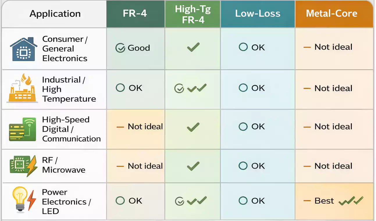
1. General Electronics / Consumer Devices
- Standard FR-4 works for most boards.
- Consider High-Tg for multi-layer or high-density designs.
- Choose low-loss materials if running high-speed interfaces (USB 3.0, HDMI, PCIe)
2. Industrial and High-Temperature Environments
- High-Tg FR-4 preferred
- Low CTE needed for repeated thermal cycling
- Consider thicker copper for power delivery.
3. High-Speed Digital & Communication Hardware
- Low-loss material is required.
- Stable Dk/Df over frequency
- Smooth copper foil reduces insertion loss.
4. RF / Microwave Circuits
- PTFE or ceramic-filled laminates
- Very low Df
- Tight impedance tolerance
5. Power Electronics and LED Thermal Applications
- Metal-core substrates
- High thermal conductivity
- Improved heat distribution under load
How Material Choice Impacts Cost and Lead Time
Many engineers underestimate the extent to which materials influence manufacturing logistics.
1. Availability
Standard FR-4 is universally stocked and offers the shortest lead times.
Low-loss and specialty materials often require:
- Supplier ordering
- Longer curing cycles
- Special processing
2. Manufacturability
Exotic materials can introduce:
- Stricter drilling parameters
- Higher lamination temperatures
- Longer press cycles
- Increased scrap risk
3. Prototype vs. Production
Some materials are easy to prototype but harder to scale into volume production.
To avoid redesigns, choose materials available in both prototype and mass-production quantities.
Common PCB Material Selection Mistakes
- Defaulting to FR-4 for High-Speed Designs
- Over-Specifying High-Performance Materials
- Ignoring Thermal Requirements
- Selecting Materials Based Only on Datasheets
- Using Different Materials for Prototype and Production
FAQ
What’s the best material for a custom PCB?
It depends entirely on your electrical, thermal, and mechanical requirements. FR-4 is common, but high-speed or high-temperature applications require alternatives.
Is FR-4 enough for most projects?
Yes—for low-speed and general-purpose electronics. Not recommended for RF or very high-speed interfaces.
When should I use High-Tg FR-4?
When your product faces thermal stress, repeated reflow cycles, or demanding industrial environments.
What is a low-loss PCB material?
A laminate engineered to minimize electrical loss at high frequencies—critical for RF and high-speed digital.
When is metal-core better?
When thermal management is the primary concern, such as with LEDs or high-power converters.
Conclusion
The right Custom PCB Material unlocks better performance, lower failure rates, and smoother manufacturing. By evaluating your electrical, thermal, and environmental requirements early, you can confidently choose between FR-4, High-Tg, low-loss laminates, and metal-core substrates.
If you need expert guidance, FastTurnPCB specializes in fast, reliable custom PCB fabrication with professional material selection support. Their engineering team can help you optimize stackup, choose the right laminate, and ensure smooth transition from prototype to production.