In modern electronics, chip resistors are among the most widely used passive components.
Whether in consumer electronics, industrial control, or automotive systems, the shape, size, marking, and terminal structure of an SMD resistor directly affect PCB manufacturability, solder reliability, and long-term performance.
This article provides an engineer-focused overview of chip resistors — covering their package types, marking systems, and technical structure — to help designers and SMT engineers choose and apply them correctly.
Chip Resistor Package Types and Manufacturing Methods
1. Package Shapes
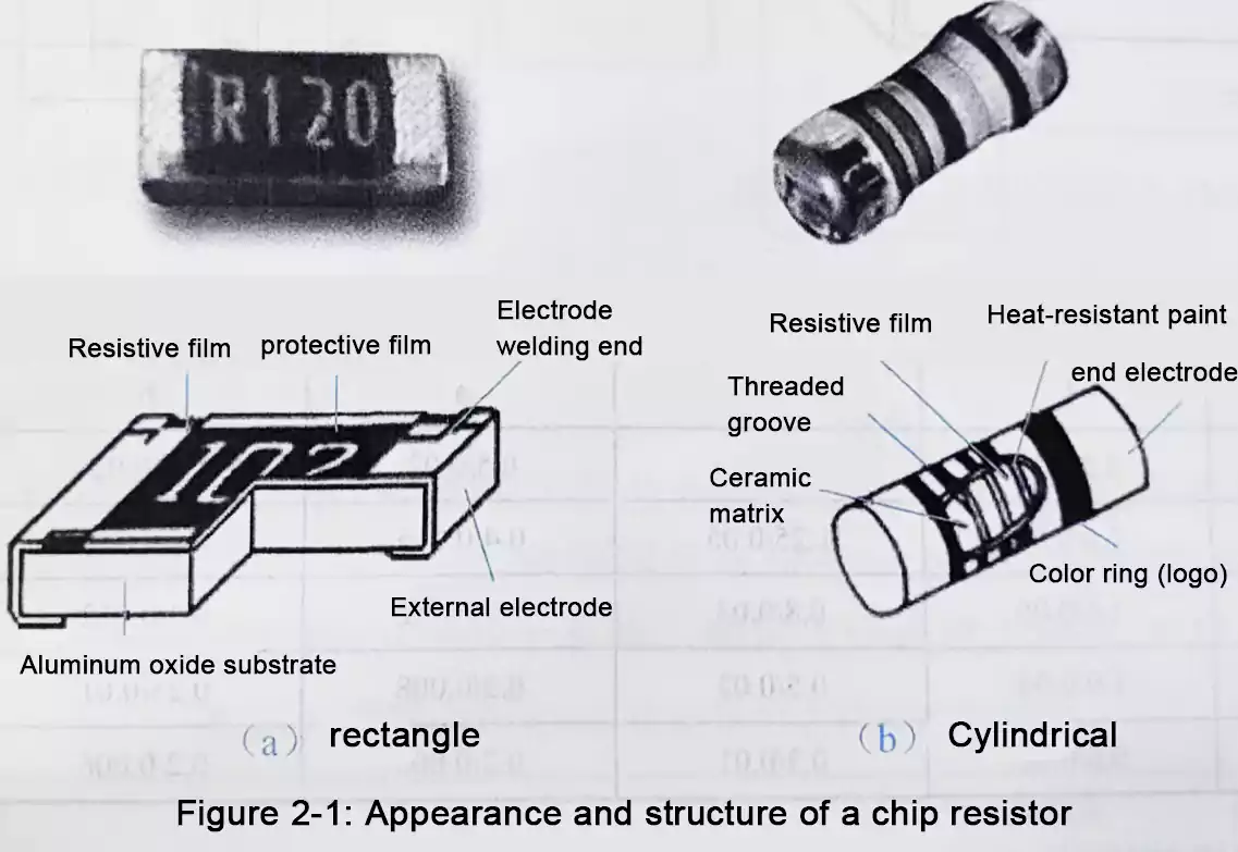
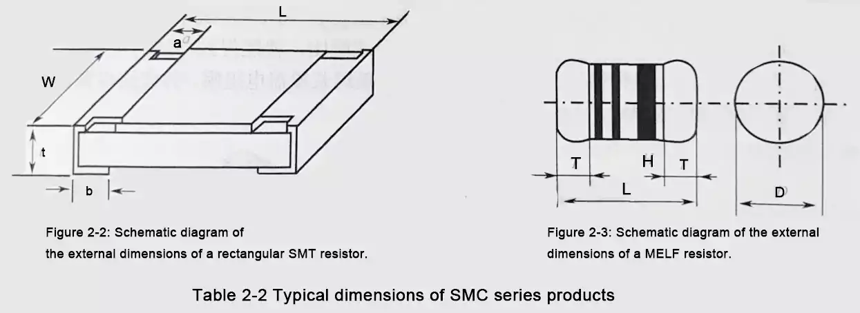
SMD resistors can be categorized into two main shapes:
- Flat rectangular chip resistors
- Cylindrical MELF resistors (Metal Electrode Leadless Face)
These two forms cover the majority of surface-mount resistor applications.
2. Manufacturing Processes
Based on fabrication technology, SMD resistors are divided into:
- Thick-film resistors (RN type)
- Thin-film resistors (RK type)
3. Thick-Film Chip Resistors
Most rectangular chip resistors are manufactured using thick-film technology.
A typical process involves:
- Using 96% alumina (Al₂O₃) ceramic as the substrate
- Screen-printing ruthenium dioxide (RuO₂) resistor paste onto the substrate.
- Adjusting resistance by changing the paste formulation or composition
- Laser trimming to fine-tune resistance values
- Applying and firing a glass protective glaze
- Forming solderable terminations at both ends
This mature process balances precision, cost, and manufacturability.
4. Cylindrical MELF Resistors
MELF resistors are typically made using thin-film technology, featuring:
- A high-alumina ceramic cylinder substrate
- A sputtered nickel-chromium (NiCr) or carbon film
- Laser-trimmed resistance grooves
- Metal end caps for soldering
- A protective coating with color bands for identification
MELF resistors are known for high reliability, temperature stability, and surge performance, making them popular in automotive and industrial circuits.
Standard Chip Resistor Sizes and Power Ratings
1. Metric vs. Imperial Codes
Chip resistors are standardized in two size systems:
- Imperial (inch-based) — commonly used in the U.S. and Europe (e.g., 0603, 0805)
- Metric (millimeter-based) — used in Japan and many Asian manufacturers (e.g., 1608, 2012)
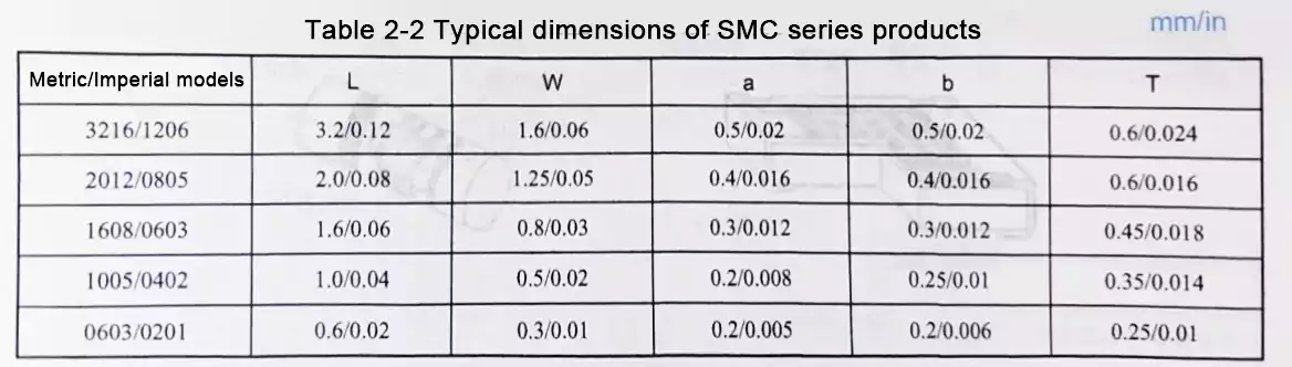
The first two digits represent length, and the last two represent width.
Example:
A 3216 (1206) resistor is 3.2 mm long and 1.6 mm wide.
2. Miniaturization Trend
The evolution of resistor sizes shows the industry’s drive toward miniaturization:
5750 → 4532 → 3225 → 3216 → 2520 → 2012 → 1608 → 1005 → 0603 → 0201
3. Typical Power Ratings
| 0201 | 1/20 W |
| 0402 | 1/16 W |
| 0603 | 1/10 W |
| 0805 | 1/8 W |
| 1206 | 1/4 W |
Underrated power dissipation is one of the leading causes of resistor failure during reflow or operation.
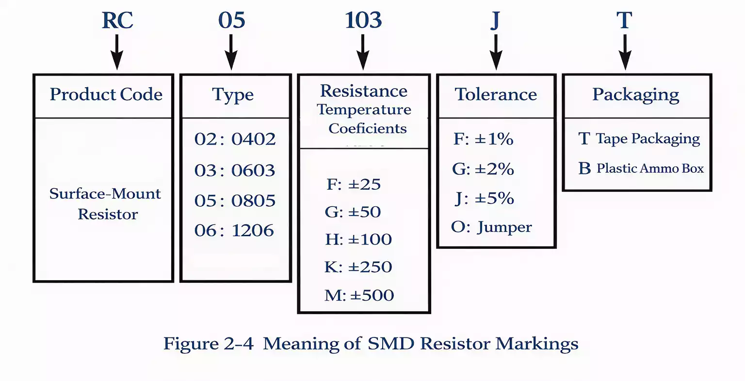
How to Read SMD Resistor Codes
The resistance values and tolerance codes for chip resistors follow the same E-series as traditional through-hole resistors:
- E6 (±20%)
- E12 (±10%)
- E24 (±5%)
- E48 (±2%)
- E96 (±1%)
Printed Codes on Chip Resistors
- Small Packages (0402, 0603, 1005)
Because of their tiny surface area, these resistors do not carry printed markings.
Values are indicated on the tape or reel packaging instead.
- Medium Packages (0805, 1206)
These often use three- or four-digit codes to mark resistance values.
3-Digit Code System (E24 Series)
- First two digits: significant figures
- Third digit: multiplier (number of zeros)
Examples:
- 114 → 110 kΩ
- 5R6 → 5.6 Ω
- R39 → 0.39 Ω
- 000 → 0 Ω jumper
4-Digit Code System (1% Tolerance)
- 2002 → 20 kΩ
- 15R5 → 15.5 Ω
- 4R80 → 4.80 Ω
MELF Color Band System
Cylindrical MELF resistors use 3-, 4-, or 5-color bands, identical to those of through-hole resistors.
Example (5-band resistor):
Green – Brown – Black – Red – Brown
→ 51 kΩ ±1%
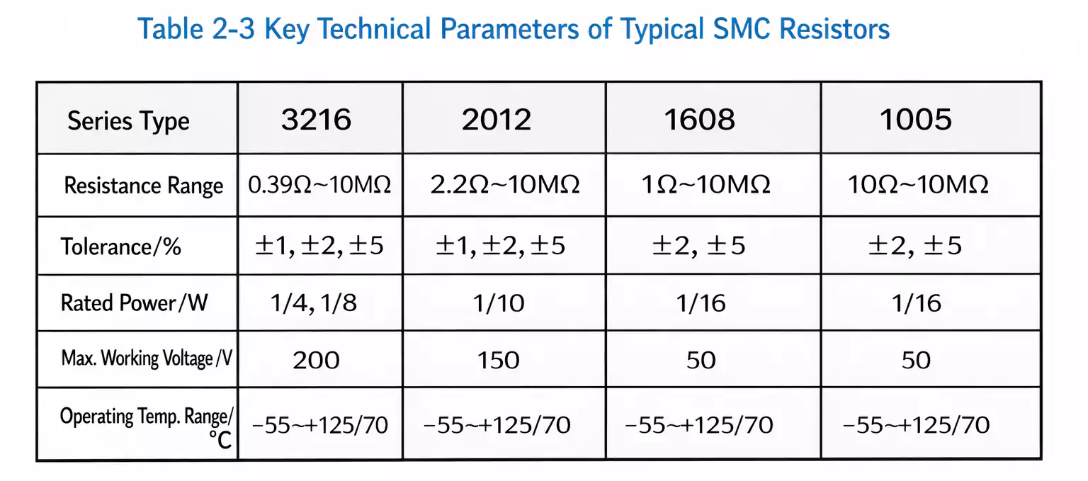
Typical Electrical Parameters of Chip Resistors
Despite their small size, chip resistors maintain wide resistance ranges and high precision.
For example, a 3216 (1206) chip resistor typically offers:
- Resistance range: 0.39 Ω to 10 MΩ
- Rated power: up to 1/4 W
- Tolerances: ±1%, ±2%, ±5%, ±10%
- Rated temperature: up to 70 °C
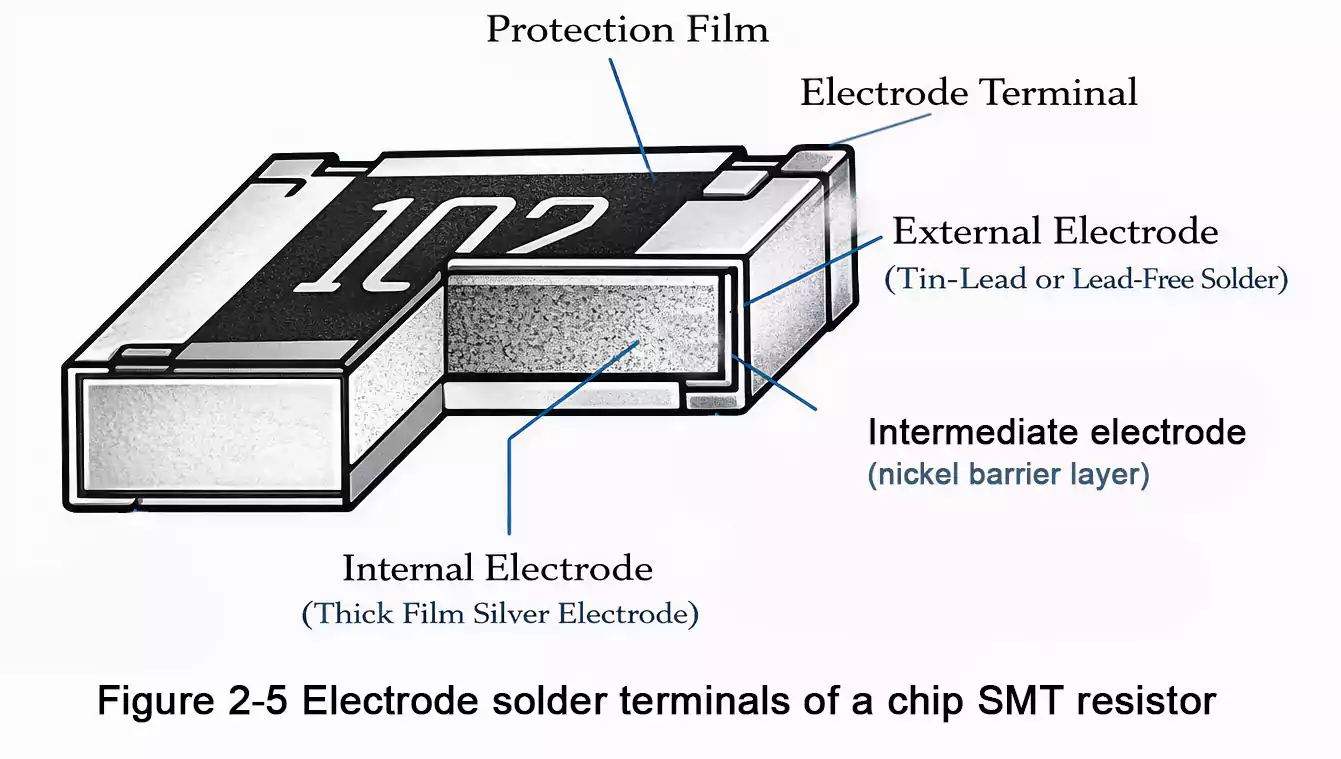
SMD Resistor Terminal Construction
1. Three-Layer Terminal Design
Chip resistor terminations usually consist of three metal layers:
- Inner electrode: Palladium–silver (Pd-Ag) alloy
- Barrier layer: Nickel (Ni)
- Outer solderable layer: Tin–lead (Sn-Pb) or lead-free alloy
2. Function of the Nickel Barrier Layer
The nickel barrier serves several critical purposes:
- Prevents intermetallic reaction between solder (Sn/Pb) and silver
- Avoids “cap lifting” or delamination during reflow
- Enhances overall solder joint reliability
Although nickel itself is not very solderable, the outer tin layer ensures good wetting during soldering.
3. Transition to Lead-Free Plating
With the global shift toward RoHS compliance, most chip resistors now use lead-free plating (Sn-Ag-Cu) to replace traditional tin-lead finishes.
FAQ
Is a chip resistor the same as an SMD resistor?
In most applications, yes.
“Chip resistor” refers to the component form, while “SMD resistor” refers to the mounting method. Rectangular chip resistors are the most common type of SMD resistor.
What are the most common chip resistor sizes?
The most common chip resistor sizes are 0402, 0603, 0805, and 1206.
Among these, 0603 and 0805 are the most widely used due to their balance of size, power rating, and ease of assembly.
How to read SMD resistor markings?
3-digit code: first two digits are the value, third digit is the multiplier
Example: 103 = 10 kΩ
4-digit code (1% tolerance): first three digits are the value, fourth digit is the multiplier
Example: 2002 = 20 kΩ
“R” notation: used as a decimal point
Example: 4R7 = 4.7 Ω
What does “000” mean on a chip resistor?
000 indicates a 0-ohm resistor, which functions as a jumper or short circuit rather than providing resistance.
What tolerance is most commonly used for chip resistors?
±5% is the most common tolerance for general-purpose circuits
±1% is commonly used in precision and signal-processing applications
Conclusion: Tiny Components, Big Impact
Chip resistors may seem simple, but their performance depends on materials, film technology, and terminal design.
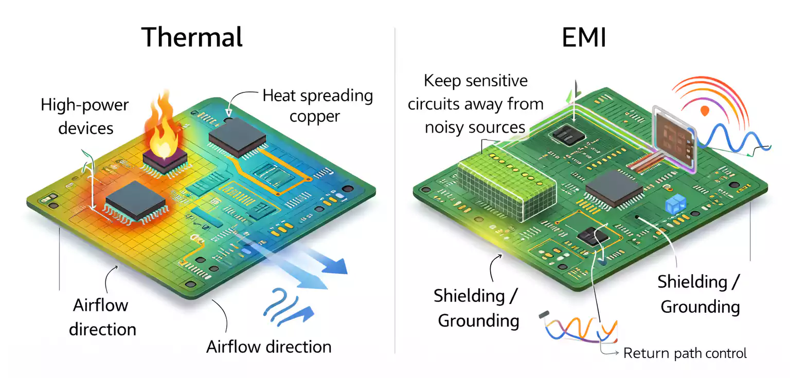
For PCB designers and SMT process engineers, understanding these details ensures better solderability, reliability, and thermal performance across the entire board.
Mastering the details of SMD resistor types — and knowing how to read SMD resistor codes — is essential for modern high-density PCB design.