When heat, reliability, or high-frequency performance becomes critical, ceramic PCBs step in where standard boards fail. Built with advanced ceramic materials like aluminum oxide (Al₂O₃) or aluminum nitride (AlN), these boards offer excellent thermal conductivity, strong insulation, and outstanding dimensional stability. Let’s take a closer look at what ceramic PCBs are, how they work, and when they’re worth the investment.
What Is a Ceramic PCB?
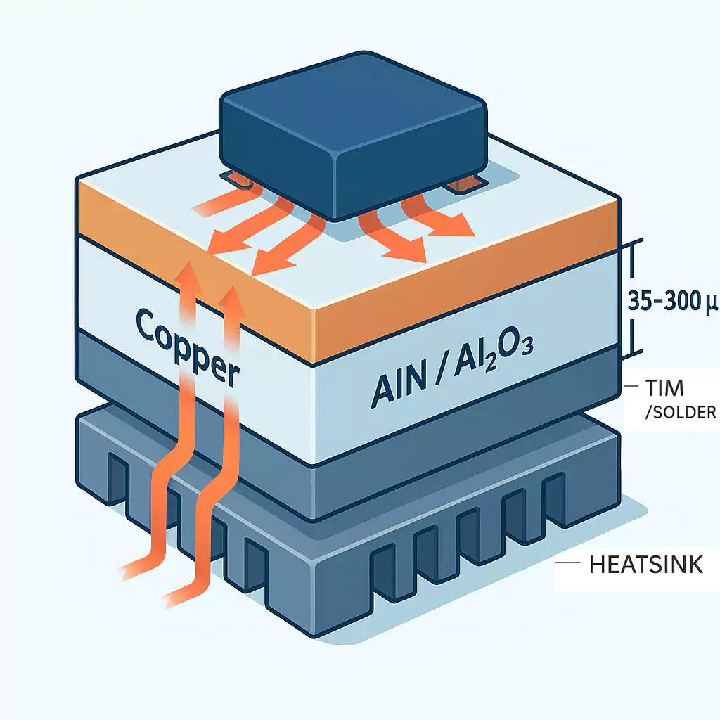
A ceramic PCB is a printed circuit board with a ceramic base rather than a traditional epoxy-glass (FR-4) or aluminum substrate. Copper traces are bonded directly to the ceramic surface via processes such as DBC (Direct Bonded Copper) or DPC (Direct Plated Copper).
With high thermal conductivity and no need for an insulating dielectric (as in metal-core PCBs), ceramic substrates let heat flow efficiently from components to heatsinks, making them ideal for high-power, high-temperature, or high-frequency electronics.
Core Materials: Al₂O₃ vs AlN
The two most common ceramic materials are aluminum oxide (Al₂O₃) and aluminum nitride (AlN).
- Al₂O₃ (Alumina): The most used ceramic base. It offers good insulation, mechanical strength, and moderate thermal conductivity (about 20–30 W/m·K). It is cost-effective and fits most medium-power or general designs.
- AlN (Aluminum Nitride): Offers excellent thermal conductivity (140–180 W/m·K) and a thermal expansion close to silicon and GaN chips. It suits high-power or temperature-sensitive devices but costs more.
Choose Al₂O₃ for an affordable step up from FR-4, and pick AlN when advanced thermal management and reliability are essential.
Why Ceramic PCBs Excel at Heat & Stability
Thermal management is the main reason designers use ceramic boards.
| FR-4 | 0.2 – 0.5 | Fiberglass epoxy, multi-layer |
| MCPCB (Aluminum base) | ≤ 10 (dielectric layer limited) | Metal base + insulation layer |
| Al₂O₃ Ceramic | 20 – 30 | Direct copper bond |
| AlN Ceramic | 140 – 180 | Direct copper bond |
Unlike FR-4 or aluminum base PCBs, ceramic boards transfer heat directly through the substrate rather than through an insulating layer. This dramatically reduces thermal resistance, allowing components to run cooler and last longer.
Ceramics maintain stable dielectric properties with low loss, making them ideal for RF, microwave, and millimeter-wave circuits. Their low coefficient of thermal expansion (CTE) reduces stress on solder joints and chips during thermal cycling.
Metallization Technologies
Ceramic PCBs use different metallization methods depending on application needs:
- DBC (Direct Bonded Copper): Thick copper bonds to ceramic under high heat. It supports high current, adhesion, and thermal cycling, common in power modules and motor drivers.
- DPC (Direct Plated Copper): Copper is plated directly on ceramic. This allows finer traces, smoother surfaces, and higher circuit density—ideal for RF, sensors, and LED arrays.
- Thick-film and Thin-film: Conductive pastes or sputtered metals create traces. These are for precision or high-frequency circuits that require tight tolerances and clean signal paths.
When to Choose Ceramic Over FR-4 or MCPCB
Ceramic boards aren’t for every project—but are unmatched in the right conditions. Consider them when:
- Heat density is high – Power modules, LED drivers, or converters where component temperature rises quickly.
- Operating frequency is high – 5G, radar, or microwave designs where dielectric loss must stay low.
- Environment is extreme – Automotive, aerospace, or industrial applications exposed to heat, vibration, or chemicals.
- Reliability is critical when solder fatigue, delamination, or dielectric breakdown is a concern.
Don’t use ceramics for very large, multi-layer logic, or cost-driven consumer boards.
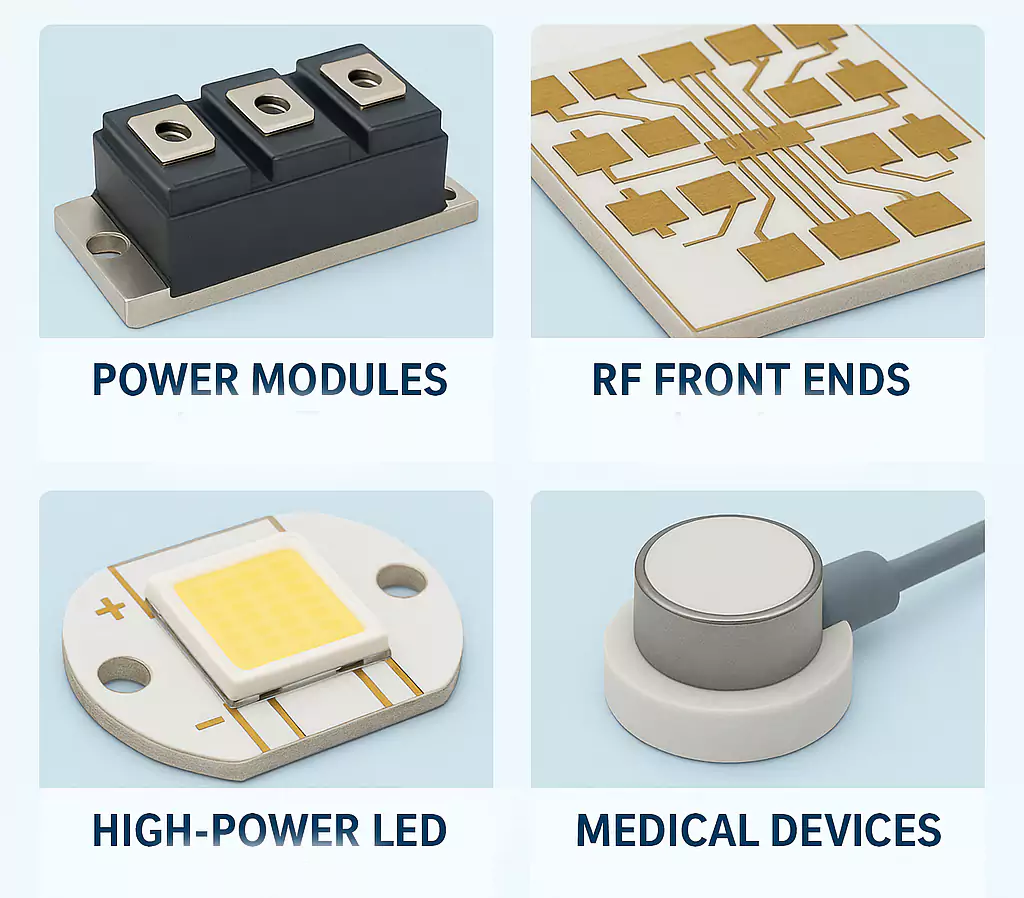
Typical Applications
- Power electronics – IGBT and MOSFET driver modules, DC-DC converters, EV inverters.
- High-brightness LEDs and lasers – Lower junction temperature extends life and color stability.
- RF and microwave – Low-loss substrates for antennas, amplifiers, and radar front ends.
- Sensors and medical electronics – High temperature, biocompatible, and stable operation.
Design and Assembly Tips
- Keep heat paths short. Mount components so heat flows directly from the die through copper and ceramic to the heatsink.
- Watch copper thickness. Thicker copper carries more current but increases cost and stress—check supplier DBC/DPC limits.
- Handle with care. Ceramics are brittle; avoid sharp corners, ensure even clamping pressure, and use proper mounting torque.
- Verify reliability. Request thermal-cycle, adhesion, and dielectric-strength test data before mass production.
Cost and Sourcing Considerations
Ceramic PCBs are more expensive than FR-4 or aluminum boards, mainly due to:
- High-grade ceramic materials (AlN, especially).
- Complex bonding or plating processes.
- Limited panel size and handling yield.
However, when total system cost is considered—smaller heatsinks, better reliability, fewer failures—the overall TCO (total cost of ownership) can be lower.
Quick FAQ
1. Is ceramic PCB better than FR-4?
Yes—when you need high thermal conductivity, temperature stability, or high-frequency performance. Otherwise, FR-4 is more economical.
2. What’s the difference between Al₂O₃ and AlN?
AlN conducts heat 5–6× better and has lower CTE, but costs more.
3. Ceramic vs Aluminum (MCPCB)?
Aluminum boards have an insulating layer that limits heat flow; ceramics conduct heat directly through the substrate.
4. Any size limitations?
Yes. Ceramic boards are typically smaller and more rigid—best under 150 × 150 mm for most manufacturers.
Conclusion
Ceramic PCBs combine superior heat dissipation, stable electrical properties, and exceptional reliability. When power density, frequency, or lifetime matter most, they outperform FR-4 and aluminum alternatives.
For engineers moving into high-power or high-frequency design, ceramic substrates like Al₂O₃ and AlN open the door to compact, cooler, and longer-lasting electronic systems.