A solderless breadboard is one of the most useful tools in electronics prototyping. It lets you build and test circuits quickly—without soldering anything. Instead of permanently attaching components to a printed circuit board, you simply plug parts and wires into a grid of interconnected holes.
Breadboards are ideal for learning, experimenting, debugging, and validating designs before moving to a PCB. Whether you’re building your first LED project or testing a new concept, a solderless breadboard enables fast, low-risk iteration.
In this guide, you’ll learn how a solderless breadboard works, how to use breadboard jumper wires correctly, how to build a simple breadboard circuit, and when it makes sense to move from a breadboard to a PCB.
What Is a Solderless Breadboard?
A solderless breadboard is a reusable prototyping platform for assembling temporary electronic circuits without soldering. Underneath the plastic surface are metal spring clips that electrically connect certain groups of holes. When you insert a component lead or jumper wire, it makes contact with those clips and becomes part of the circuit.
The main advantage of a solderless breadboard is flexibility. You can quickly move components, change resistor values, reroute connections, and rebuild circuits. Nothing is permanent.
That’s why breadboards are widely used in:
- Electronics education
- Hobby projects
- Lab testing
- Early-stage product development
- Proof-of-concept validation
Unlike a printed circuit board, a solderless breadboard is not intended for final production. It’s a temporary workspace where ideas can evolve quickly.
Why Engineers and Beginners Use Breadboards
Breadboards remain popular because they make experimentation easy.
You don’t need a soldering iron. You don’t need to commit to a layout. And you don’t risk damaging components during assembly.
For beginners, breadboards make abstract electrical concepts more visible. You can physically see how current flows from power to load to ground.
For engineers, breadboards are useful during early testing. Before designing a custom PCB, you can validate your circuit logic, confirm voltage levels, or test a sensor interface.
They’re fast, reusable, and forgiving—ideal during the learning and exploration phase.
How a Breadboard Works
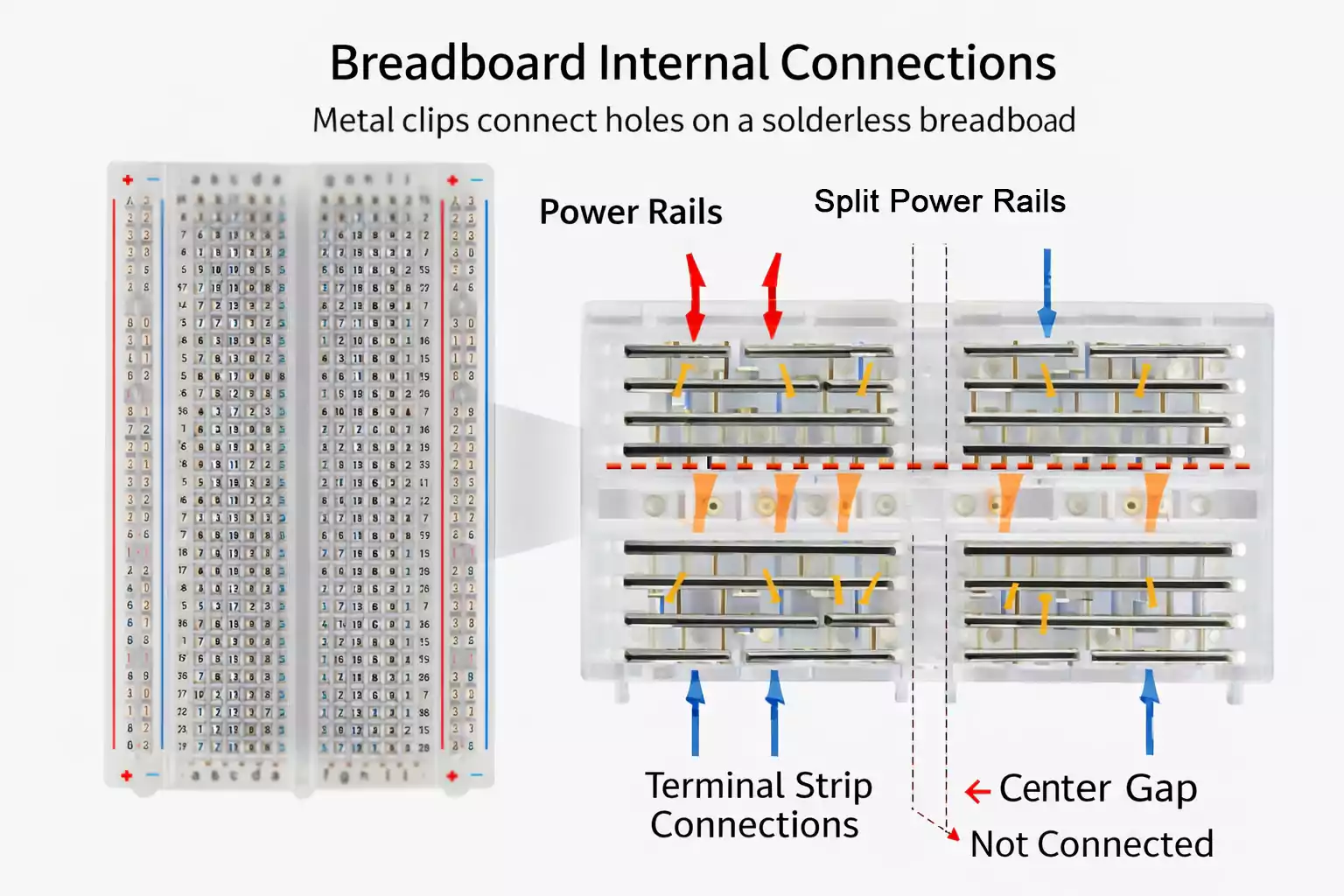
Understanding the internal connections is the key to using a breadboard correctly.
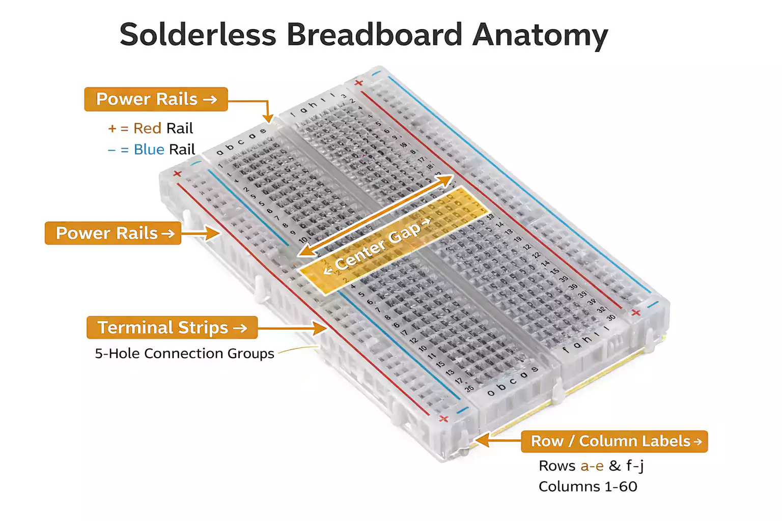
Terminal Strips
The central working area of a breadboard is divided into small connection groups. In most standard boards, each horizontal group of five holes is electrically connected underneath.
If you place a resistor lead in one hole and a jumper wire in another hole within the same group, the resistor and the jumper wire are electrically connected.
However, those five-hole groups are isolated from adjacent groups. Just because two holes are next to each other visually does not mean they are connected.
Power Rails
Along the outer edges of many breadboards are long strips labeled with plus (+) and minus (−) signs. These are power rails.
They’re designed to distribute voltage and ground across the board, so you don’t need separate power wires everywhere.
For example:
- Connect 5V to the positive rail.
- Connect the ground to the negative rail.
- Then tap into those rails wherever your circuit needs power.
Some breadboards split their power rails in the middle. That means the top half may not automatically connect to the bottom half.
The Center Gap
The gap running down the center of the board is there for dual-in-line package (DIP) integrated circuits.
When you place a DIP IC across the gap:
- The pins on the left connect to the terminal strips on one side.
- The pins on the right connect to the opposite side.
Without that gap, opposite pins could accidentally short together. The center channel keeps things separated and organized.
Hole Spacing and Standard Pitch
Most solderless breadboards use a 0.1-inch (2.54 mm) hole spacing. This standard pitch matches many through-hole components and header pins.
That’s why resistors, LEDs, DIP chips, push buttons, and many modules fit so neatly.
How to Read Breadboard Rows, Columns, and Labels
Breadboards usually include printed letters and numbers along the edges. These are simply coordinates to help you identify locations.
For example, a tutorial might say:
“Insert the resistor into row E10.”
That just tells you where to place it. The labeling does not create any electrical connection by itself—it’s just a reference system.
Similarly, the + and − markings near the power rails are guides. They indicate intended use but do not guarantee how the rails are internally connected. Always verify before wiring.
What Components Work Best on a Solderless Breadboard?
Breadboards are optimized for through-hole components.
Common compatible parts include:
- Resistors
- Capacitors with leads
- LEDs
- Diodes
- Small transistors
- DIP ICs
- Push buttons
- Pin headers
- Sensor modules with 2.54 mm headers
Surface-mount components generally do not plug directly into breadboards. If you need to use them, you’ll typically mount them on an adapter or breakout board first.
Also, remember that breadboards are best for low-voltage, low-current, and low-frequency circuits. They are not suitable for high-power applications or high-speed RF designs.
Breadboard Jumper Wires Explained
Breadboard jumper wires are what bring your circuit to life. They connect isolated nodes, distribute power, and complete signal paths.
What Are Jumper Wires Used For?
Jumper wires link different rows, bridge power rails, and connect modules or components that are not directly aligned.
Without jumper wires, most breadboard circuits would not function beyond a few directly adjacent parts.
Male-to-Male vs. Male-to-Female
Male-to-male jumper wires are the most common type for breadboard use. Both ends plug directly into the board.
Male-to-female wires are useful for connecting a breadboard to development boards or modules with exposed male header pins.
Female-to-female wires are less common for breadboard-only builds but are useful when linking modules together.
Solid-Core vs. Flexible Jumper Wires
Solid-core jumper wires are often preferred for breadboard work. They hold their shape, insert securely, and keep the layout neat.
Flexible jumper wires are convenient for quick setups and external connections, but too many can make the board messy.
Solid wires for clean internal routing, flexible wires for connecting external boards or power supplies.
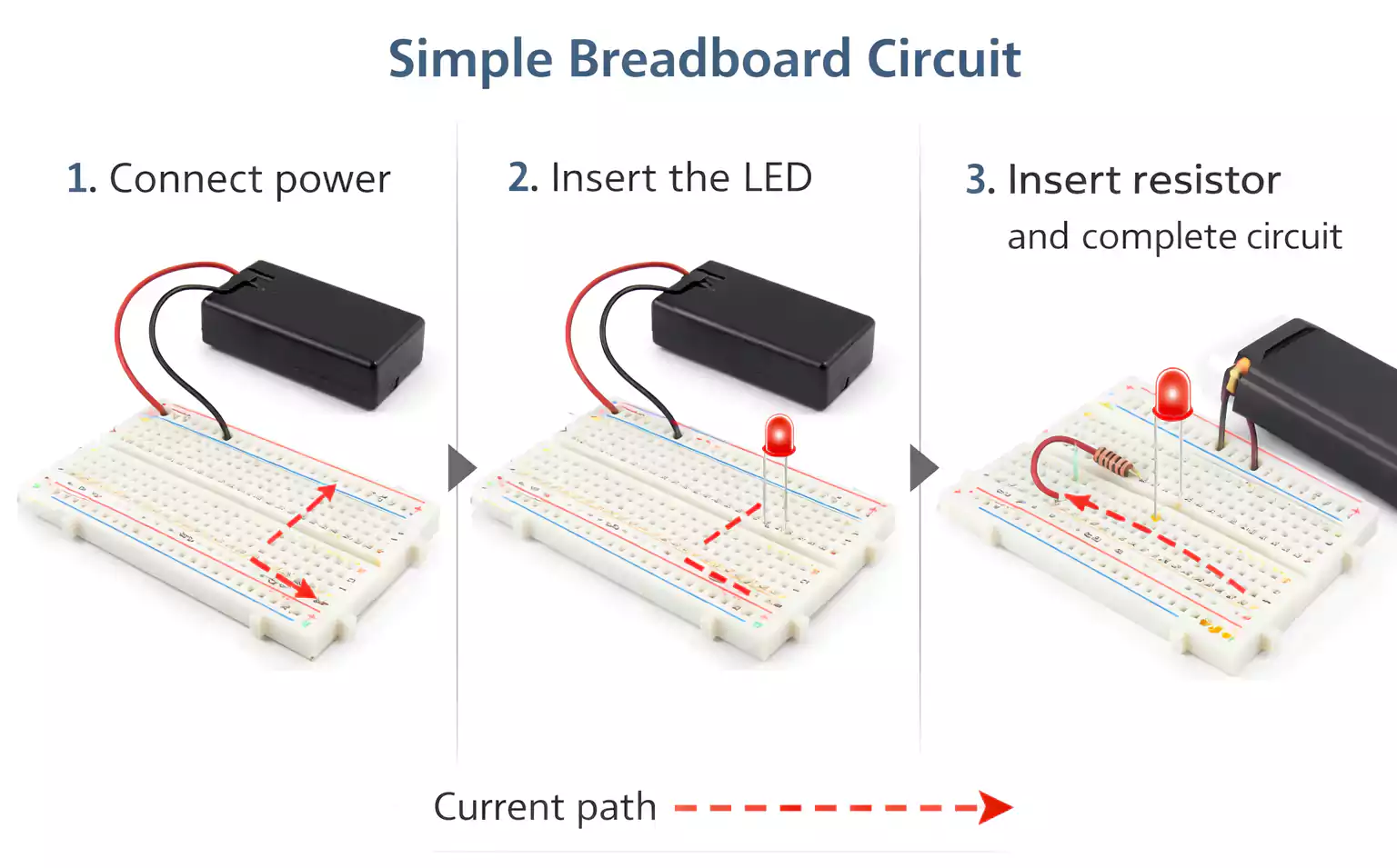
How to Build a Simple Breadboard Circuit
A basic LED circuit is a perfect first project. It demonstrates how power flows and how series connections work.
What You’ll Need
- 1 solderless breadboard
- 1 LED
- 1 resistor (220–330 ohms)
- 5V power source or battery pack
- Jumper wires
Step 1: Connect Power
Connect your positive voltage to the positive power rail. Connect the ground to the negative rail.
If the rails are split, bridge them with a jumper wire if necessary.
Step 2: Insert the LED
Place the LED so that its two legs sit in different connected rows. Do not insert both legs into the same five-hole group.
The longer leg (anode) should face toward the positive side.
Step 3: Add the Resistor
Insert one end of the resistor into the same row as the LED’s anode or cathode (depending on your layout). Place the other end into a new row.
The resistor limits current and protects the LED.
Step 4: Complete the Circuit
Use jumper wires to connect:
- Positive rail → resistor
- LED → ground rail
Now you have a complete series path: power → resistor → LED → ground.
Step 5: Test and Troubleshoot
If the LED does not light:
- Check polarity.
- Verify the resistor is in series, not bypassed.
- Confirm row placement.
- Make sure power rails are active.
- Push wires in firmly.
This simple breadboard circuit builds foundational troubleshooting skills.
How to Read a Breadboard Diagram
A breadboard diagram shows the physical placement of components. It differs from a schematic diagram, which focuses purely on electrical relationships.
Two breadboard layouts may look different, but still function identically if the electrical connections are correct.
When starting out, follow the diagram closely. As you gain experience, you’ll become more comfortable rearranging layouts while maintaining the same electrical nodes.
Common Breadboard Mistakes
Even simple projects can fail due to small layout errors.
Common issues include:
- Placing both leads of a component in the same connected row
- Assuming power rails are automatically continuous
- Loose or partially inserted jumper wires
- Reversing polarized components
- Overcrowded wiring that hides mistakes
Keeping your layout clean and organized makes debugging much easier.
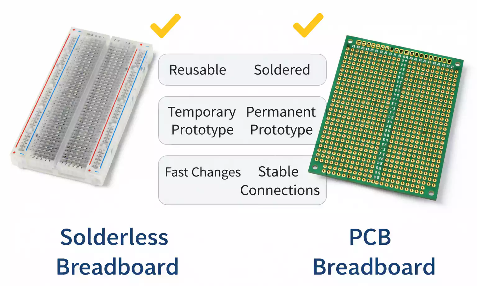
Solderless Breadboard vs. PCB Breadboard
A solderless breadboard is temporary. A PCB breadboard—often called a solderable prototyping board—is permanent.
With a solderable board, you replicate your working circuit and solder components in place. The connections become stable and durable.
The solderless version is ideal for experimenting. The PCB version is better once the design is finalized.
What is a full-sized breadboard PCB?
A full-sized breadboard PCB typically mimics the layout of a full-size breadboard. It allows you to transfer a proven design into a more robust format without redesigning everything.
This is useful when you want improved reliability but are not yet ready for a fully custom PCB layout.
When to Move from a Breadboard to a PCB
Breadboards are excellent for testing—but not for finished products.
You should consider moving to a PCB when:
- Your circuit design is finalized.
- You need stronger, permanent connections.
- The project must fit inside an enclosure.
- You want a cleaner signal routing.
- Long-term reliability matters
A proper PCB provides mechanical strength, repeatability, and improved electrical performance.
Final Thoughts
A solderless breadboard remains one of the most practical tools for learning and prototyping electronics. It lowers the barrier to experimentation and helps you move quickly from concept to working circuit.
Once your breadboard circuit is stable and validated, transitioning to a PCB is the natural next step.
If you’re ready to move from a temporary prototype to a production-ready design, FastTurnPCB can help you bring your circuit from breadboard to a professionally manufactured PCB.
