Introduction
A .gbr file is most commonly known as a Gerber file, the standard format used in PCB (Printed Circuit Board) manufacturing to define copper layers, solder masks, silkscreens, and drilling data. It plays a critical role in translating a PCB design into physical fabrication instructions readable by CAM (Computer-Aided Manufacturing) systems.
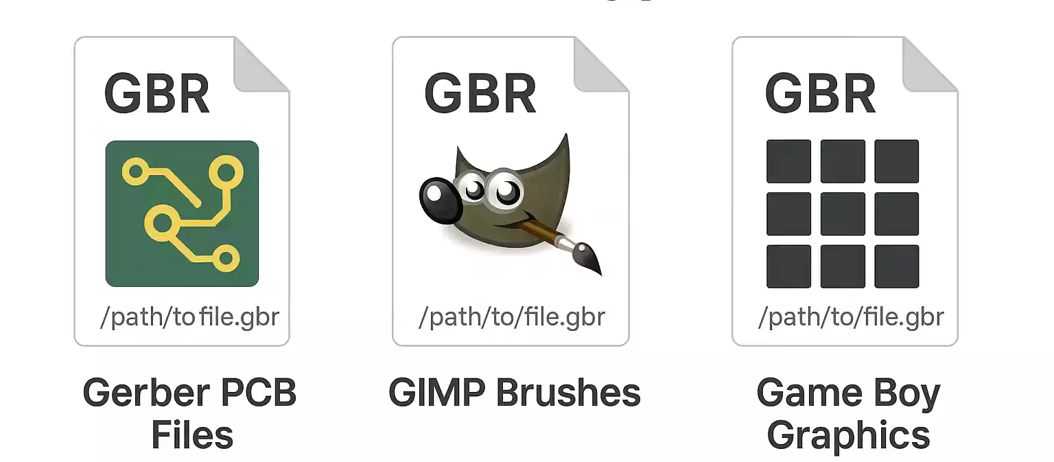
While the term "GBR file" may also refer to other formats—such as GIMP brush files or legacy video game assets—this article focuses primarily on its use in electronics design and manufacturing. It covers the structure and evolution of the Gerber format, supported tools for viewing and conversion, best practices for file preparation, and common troubleshooting steps.
GBR File Types Explained & Compared
While Gerber files dominate in PCB manufacturing, other GBR file types are found in image editing software and retro game development. The table below provides a quick comparison:
Common GBR File Types
| File Type | Primary Use | Associated Software | Description |
|---|---|---|---|
Gerber File (.gbr) | PCB design & fabrication | Altium Designer, KiCad, Eagle, Gerbv | Industry-standard file format for describing PCB layers and drill data. Used by manufacturers to fabricate printed circuit boards. |
GIMP Brush File (.gbr) | Digital image editing | GIMP | Custom brush file used in GIMP (GNU Image Manipulation Program) for digital painting and design. Contains bitmap data and metadata like spacing. |
Game Boy Tile File (.gbr) | Game development / emulation tools | Game Boy dev tools, Tile Layer Pro | Stores tile graphics used in older Game Boy games. Mostly found in ROM hacking or legacy game development environments. |
DNA Sequence File (.gbr) | Genomic data (less common) | SnapGene, GenBank | Occasionally used as a shorthand for GenBank records (.gb/.gbk), but this usage is rare and unofficial. |
Gerber Format Essentials: GBR Files in PCB Manufacturing
In the context of electronics, a .gbr file is most commonly a Gerber file—the industry-standard format used to describe the physical layers of a printed circuit board (PCB) for manufacturing. These files serve as precise blueprints, guiding fabrication machines on where to place copper traces, apply solder masks, drill holes, and print silkscreen labels.
What Is the Gerber Format?
The Gerber format, maintained by Ucamco, is a vector-based file specification that represents various PCB layers. Each Gerber file corresponds to one layer or process step in the PCB manufacturing workflow.
There are three main Gerber formats:
| Format | Description |
|---|---|
| RS-274D | Outdated format requiring separate aperture files; no longer recommended. |
| RS-274X (Gerber X1) | Modern format with embedded aperture data; widely used in industry. |
| Gerber X2/X3 | Enhanced versions with embedded layer metadata, component info, and netlist references. |
Common Gerber File Layer Types
Each Gerber file is named and exported according to the specific PCB layer or function it represents. A typical PCB design may include the following .gbr files:
| Layer Type | Description | Example Filename |
|---|---|---|
| Top Copper | Conductive traces and pads on the top layer of the PCB | TopCopper.gbr or F_Cu.gbr |
| Bottom Copper | Bottom-layer traces and pads | BottomCopper.gbr or B_Cu.gbr |
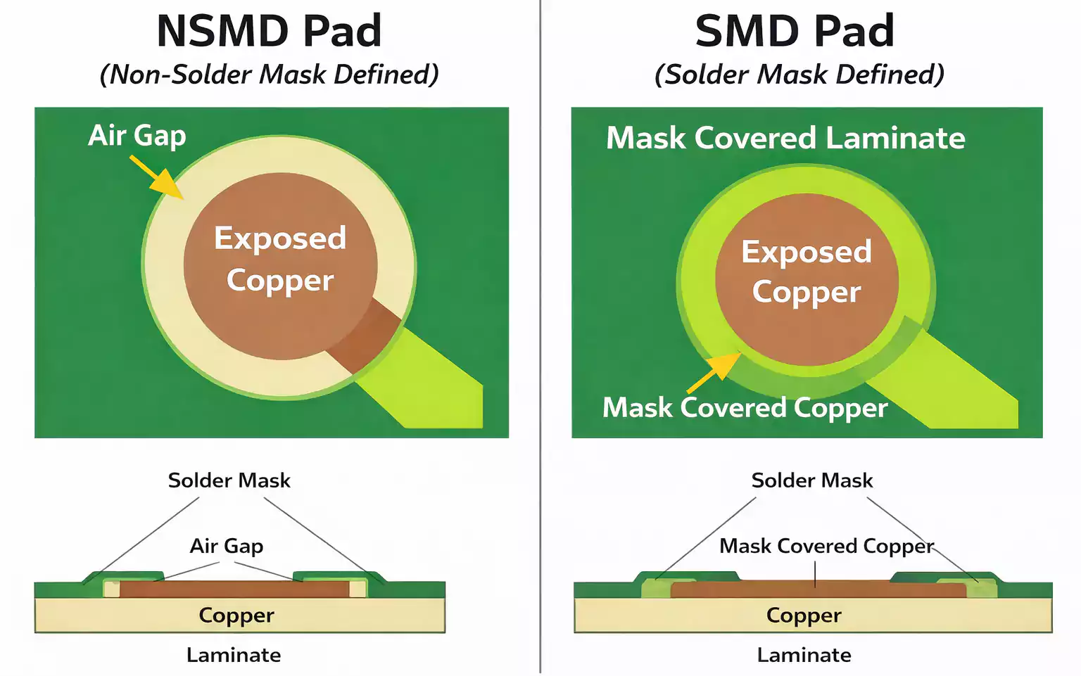
| Solder Mask (Top) | Defines areas where solder mask is applied to the top layer | TopMask.gbr or F_Mask.gbr |
| Silkscreen (Top) | Text and graphics printed on the top of the board | TopSilkscreen.gbr or F_Silk.gbr |
| Board Outline | Defines the mechanical edges of the PCB | BoardOutline.gbr or EdgeCuts.gbr |
| Drill File | Describes hole locations and tool sizes (not a .gbr, usually .drl) | Drill.drl |
Generating and Viewing Gerber Files
Gerber files are the industry-standard output for PCB manufacturing. Once a PCB design is complete, the designer exports each layer—such as copper, silkscreen, solder mask, and drill data—into separate .gbr files. These files are then submitted to a PCB fabrication house for production. Accurate generation and visual verification of Gerber files are essential to prevent costly manufacturing errors.
How to Generate Gerber Files in Popular EDA Tools
Most electronic design automation (EDA) software platforms support Gerber file export. Here's a summary of how to generate them in the most commonly used tools:
| EDA Software | Export Method |
|---|---|
| KiCad | Use Plot under the PCB Editor → Select Gerber format → Choose layers → Generate Drill Files → Export. |
| Altium Designer | Use File → Fabrication Outputs → Gerber Files → Configure layers and aperture settings → Export. |
| EAGLE | Use CAM Processor → Load the "gerber.cam" job file → Process Job → Export to folder. |
| EasyEDA | Click Fabrication Output → Select Gerber → Download ZIP file with all layers. |
| OrCAD / Allegro | Use Artwork Output function → Configure film control → Export each layer as a Gerber file. |
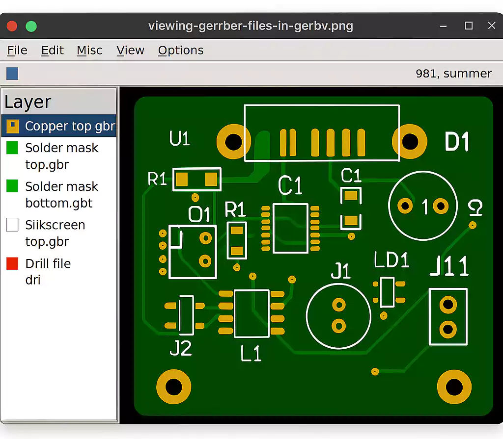
Recommended Gerber File Viewers
After generating Gerber files, it's critical to verify them using a dedicated viewer. These tools allow you to inspect each layer, check alignment, and confirm drill positions before submitting to the manufacturer.
| Gerber Viewer | Platform | Key Features |
|---|---|---|
| Gerbv | Windows/Linux/macOS | Free, open-source viewer maintained by the KiCad team. Supports RS-274X. |
| GC-Prevue | Windows | Industry-standard CAM viewer with advanced layer controls and measurement tools. |
| ViewMate | Windows | Professional-grade viewer for inspecting and editing Gerber files. |
| ZofzPCB | Windows | 3D Gerber viewer for visualizing full PCB stacks and drill depths. |
| Online Gerber Viewer | Web-based | No installation needed; ideal for quick checks. (e.g., EasyEDA Viewer) |
Gerber File Validation & Troubleshooting (QC Workflow)
Before submitting Gerber files to a PCB manufacturer, a thorough validation process is essential. Errors in Gerber files can result in production delays, increased costs, or non-functional boards. A robust quality control (QC) workflow ensures that every layer is correctly exported, aligned, and compliant with fabrication standards.
Key Areas to Verify in Gerber Files
| Checkpoint | Description |
|---|---|
| Layer Completeness | Ensure all necessary layers are present: top/bottom copper, solder mask, silkscreen, drill, and board outline. |
| File Naming Consistency | Use clear, standardized names (e.g., TopCopper.gbr, BottomMask.gbr, BoardOutline.gbr). Avoid ambiguous or default names. |
| Units & Format Settings | Confirm settings (mm vs. inch, 2:5 or 2:6 format) match manufacturer requirements. |
| Drill File Inclusion | Always include Excellon drill files (.drl) with proper tool mapping and zero suppression settings. |
| Aperture Definitions | For RS‑274‑D, ensure apertures are defined separately or use RS‑274‑X/X2 for embedded definitions. |
| Zero Suppression Consistency | Check leading/trailing zero suppression settings are uniform across all files. |
| Polarity and Overlaps | Make sure fills and negatives (clearances) are correctly defined. Avoid overlapping polygons. |
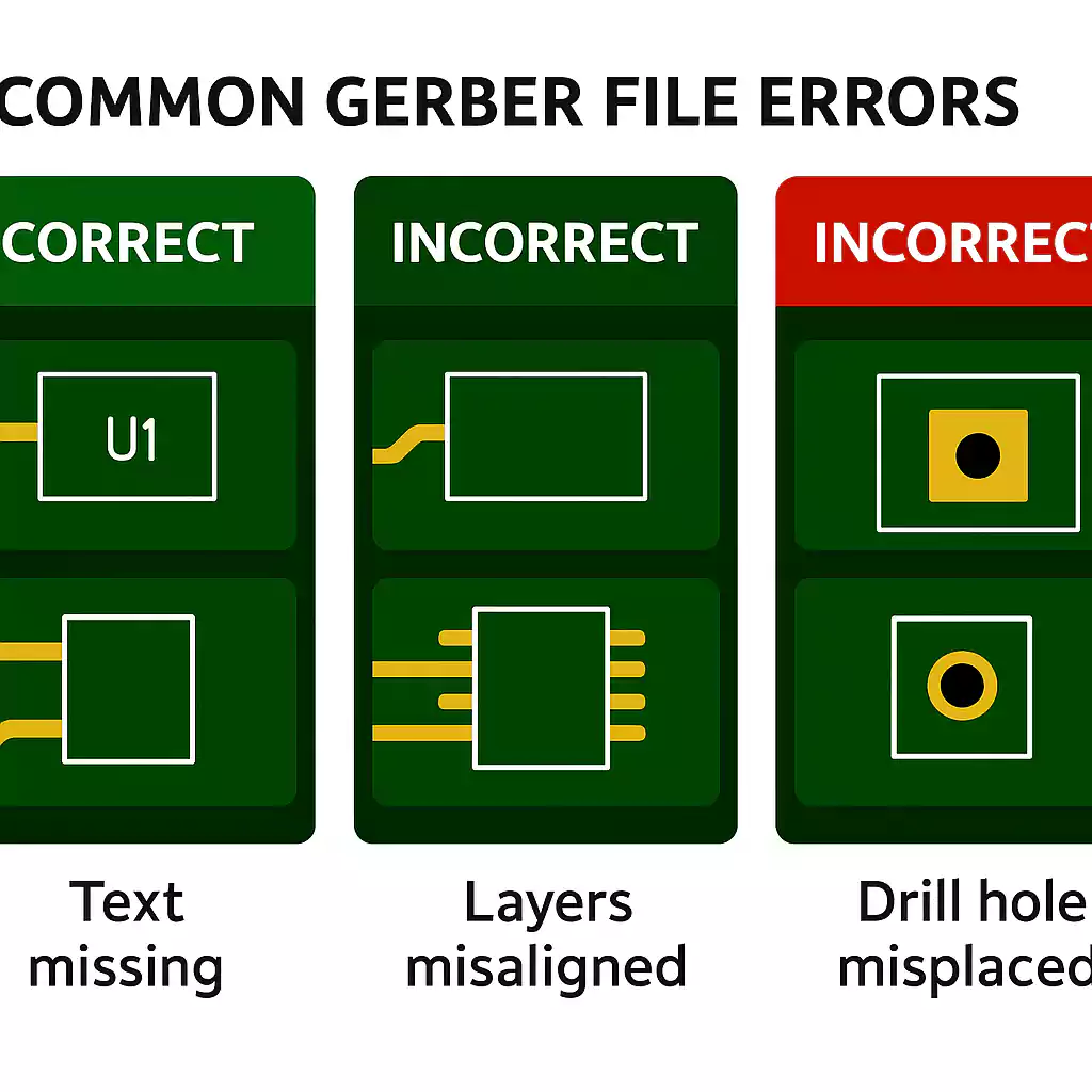
Common Gerber File Issues and Fixes
| Problem | Cause | Recommended Fix |
|---|---|---|
| Missing drill holes | Drill file not included or improperly mapped | Regenerate drill file with matching format specs |
| Text not visible or distorted | Font not converted to vector | Use stroke-based fonts; avoid TrueType fonts |
| Layer misalignment | Origin offset or unit mismatch | Align all layers to the same origin and units |
| Clearances not respected | DRC not run or incorrect design rules | Run DRC in EDA software and fix violations |
| Extra or duplicate layers | CAM export misconfigured | Review CAM job setup and regenerate files |
A disciplined QC workflow is critical in PCB design. By validating Gerber files thoroughly and using industry-recommended tools, designers can avoid re-spins and ensure seamless transition from design to manufacturing.
Frequently Asked Questions (FAQ)
What is a .gbr file and how is it used?
A .gbr file is typically a Gerber file used in PCB manufacturing to describe individual board layers, such as copper traces, solder masks, and silkscreens. Fabricators use these files to build physical circuit boards directly from the digital layout.
How do I open a .gbr file?
You can open .gbr files using dedicated Gerber viewers like Gerbv, GC-Prevue, ViewMate, or ZofzPCB. These tools allow you to visually inspect each layer before sending files to a PCB manufacturer.
What software can generate Gerber files?
Popular EDA tools like KiCad, Altium Designer, Autodesk Eagle, and EasyEDA can generate Gerber files. Each software provides a CAM export or “Plot” feature to create standard .gbr outputs.
Can I convert Gerber (.gbr) files to PDF or image formats?
Yes. Tools like Gerbv, ViewMate, and many online Gerber viewers support conversion to PDF, PNG, or SVG formats. This is useful for documentation and client approvals.
Why won't my Gerber file display correctly in a viewer?
Display issues often stem from missing drill files, incorrect layer alignment, or mismatched format settings (units, zero suppression). Ensure all related files are included and settings match the viewer’s requirements.
What's the difference between Gerber RS-274X, X2, and X3?
RS-274X is the standard Gerber format with embedded aperture definitions. RS-274X2 adds attributes like netlist and component data, while X3 (still emerging) includes stack-up and layer order metadata for advanced automation.
Do I need to include a drill file with my Gerber files?
Yes. Drill files (typically .drl or .txt) are required to define the position and size of holes and vias. Without them, your board cannot be manufactured accurately.
Can I edit a .gbr file after export?
Gerber files are not meant to be edited like CAD files. However, some tools like ViewMate Pro or CAM350 allow minor modifications. For design changes, it’s best to edit the original PCB layout and re-export.
How should I name my Gerber files?
Use clear, descriptive names such as TopCopper.gbr, BottomMask.gbr, and DrillFile.drl. Avoid generic names like layer1.gbr to help fabricators identify each file quickly and reduce risk of errors.
What if my manufacturer reports errors in my Gerber files?
Use a Gerber viewer to reproduce the issue, then re-export the files with corrected settings. Double-check origin alignment, units, and drill file compatibility. Many manufacturers also provide DFM reports to help identify problems.
Conclusion
Understanding the structure, usage, and proper handling of .gbr files—especially Gerber files used in PCB manufacturing—is essential for engineers, designers, and electronics professionals. From file generation in EDA tools to viewing, validating, converting, and packaging them for production, each step plays a critical role in ensuring accurate and manufacturable printed circuit boards.
This guide has covered:
- What a GBR file is and how it varies by context
- How to generate and view Gerber files using industry-standard tools
- Quality control (QC) workflows and common troubleshooting techniques
- Best practices for converting and sharing files with PCB manufacturers
- Advanced tips and answers to the most frequently asked questions
Whether you're preparing a design for prototyping or submitting files to a high-volume PCB fabricator, following these best practices can help you avoid costly delays and improve the reliability of your designs.