

Aluminum PCBs, or metal-core PCBs (MCPCBs), combine strength, thermal conductivity, and reliability. They’re widely used in LED lighting, power supplies, and ballast circuits needing efficient heat dissipation. This guide covers how aluminum PCBs work, their structure, failure points, and assembly tips, with ballast and LED power applications as examples.
What Is an Aluminum PCB?
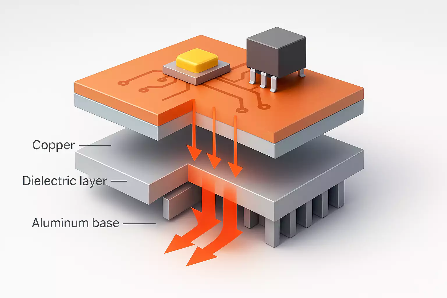
An aluminum PCB is a metal-core printed circuit board designed for rapid heat dissipation. Unlike FR-4 boards, it has a metal base—usually aluminum—bonded to a thin dielectric layer and a copper circuit layer.
Typical structure (top to bottom):
- Copper layer – Conducts electrical signals and distributes heat.
- Dielectric layer – A thin thermally conductive but electrically insulating layer.
- Aluminum base – Provides mechanical strength and acts as a heat spreader.
This three-layer stack is sometimes called a “thermal sandwich.” The dielectric layer plays the most critical role—it transfers heat from the copper traces down into the aluminum base while keeping the circuit electrically isolated.
Why Use Aluminum PCBs?
The main advantage is heat management. Aluminum has a thermal conductivity of about 200 W/m·K, compared with FR-4’s 0.3 W/m·K. While the dielectric layer slows transfer slightly, performance remains far better than fiberglass-based boards.
That makes aluminum PCBs ideal for:
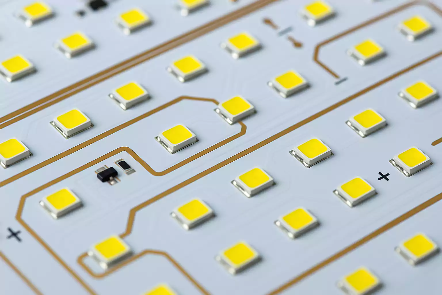
- LED lighting and drivers
- Electronic ballasts and power supplies
- Automotive and street lighting systems
- Power amplifiers and industrial controls
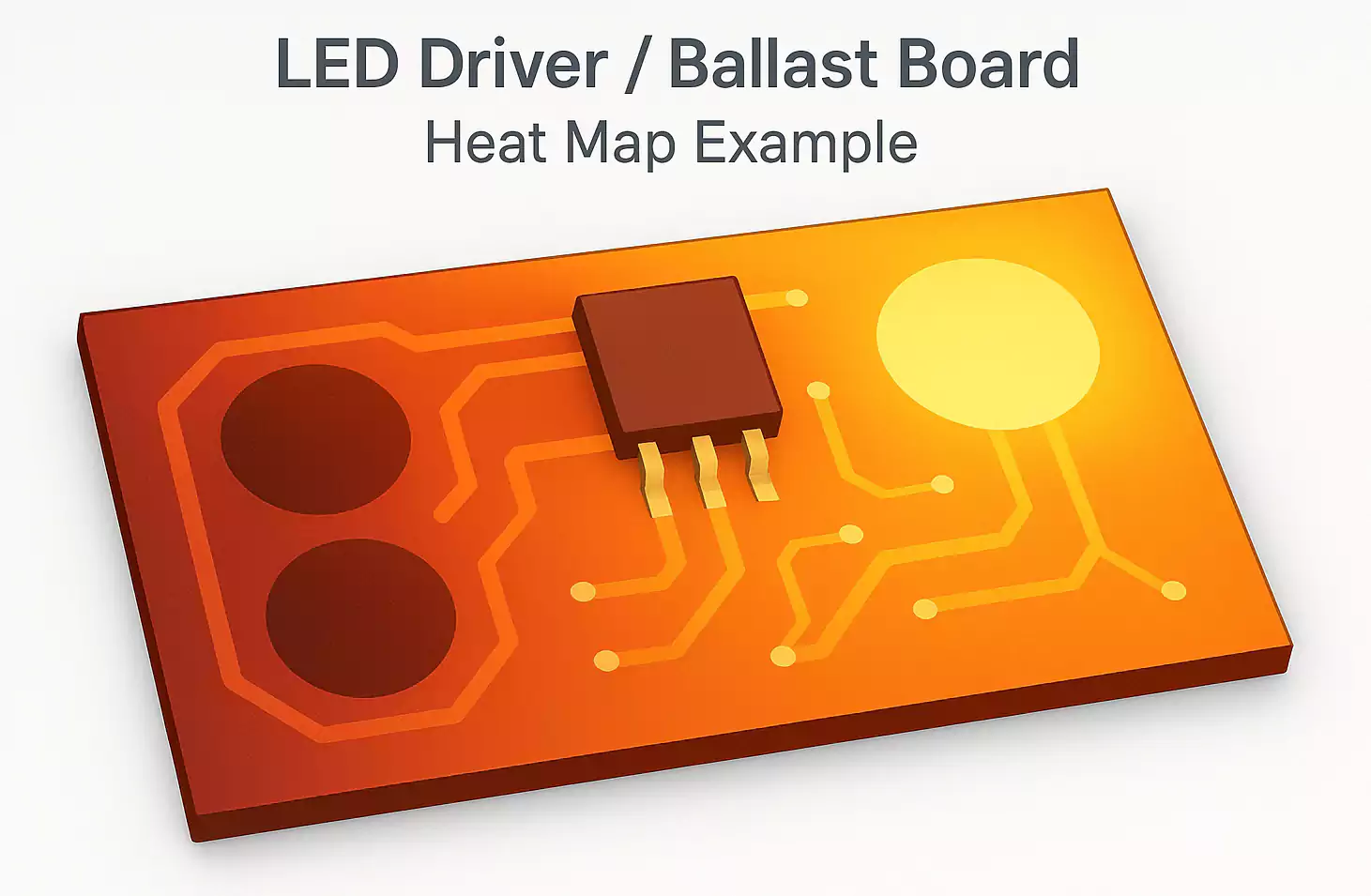
In an LED driver or ballast, components like MOSFETs, rectifiers, and LEDs generate significant heat. If unmanaged, this reduces efficiency and lifespan. Aluminum PCBs transfer heat efficiently to a heat sink or enclosure.
MCPCB Thermal Path Explained
In a well-designed aluminum PCB, the heat path flows like this:
Chip → Solder joint → Copper foil → Dielectric layer → Aluminum base → Housing or heat sink.
Each layer should have minimal thermal resistance. The dielectric layer is the main bottleneck, so its conductivity (1–3 W/m·K) and thickness (75–150 µm) are key. Thinner, higher-conductivity dielectrics provide better heat flow but lower breakdown voltage. Designers balance these tradeoffs based on voltage and temperature.
Types of Aluminum PCBs
1. Single-sided MCPCB – The most common structure, used in LEDs and simple power circuits.
2. Double-sided MCPCB – Includes vias or plated holes connecting copper on both sides, allowing denser routing.
3. Multilayer hybrid – Combines FR-4 or polyimide cores with aluminum for high-current or control-plus-power combinations.
Some manufacturers offer copper- or steel-based MCPCBs, but aluminum offers the best balance of cost, weight, and heat performance.
Ballast and LED Driver Example
In LED power supplies or ballasts, heat sources include switching MOSFETs, diodes, and LED arrays. These devices mount on aluminum PCBs to draw heat into the metal core.
Key design practices:
- Use larger copper pads and thicker copper (2–3 oz) for high-current paths.
- Place hot components near mounting holes or contact areas connected to the heat sink.
- Maintain adequate creepage distance between high-voltage and low-voltage regions.
- Add thermal vias or local copper planes under power ICs when using hybrid (FR-4 + aluminum) boards.
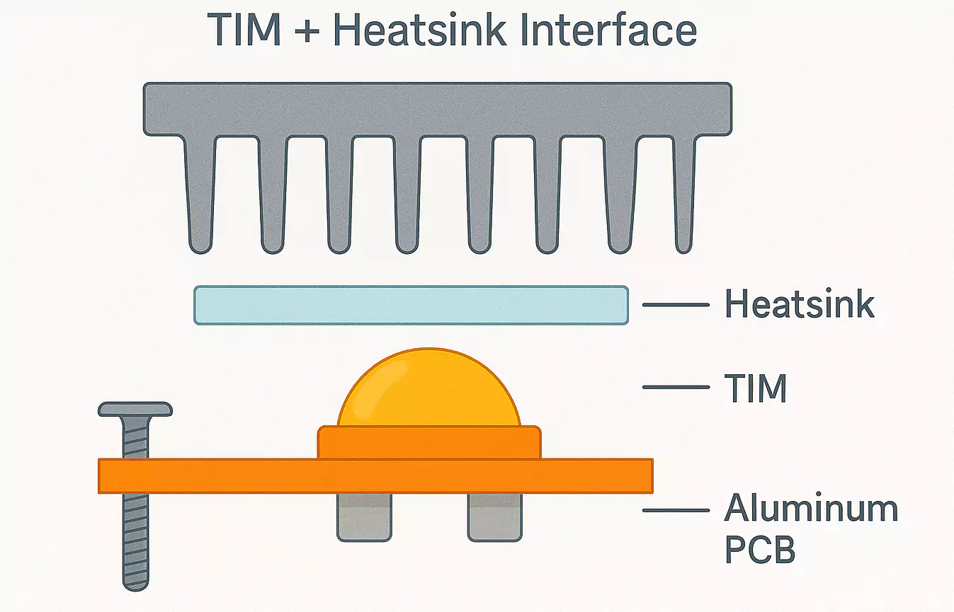
- Apply thermal interface materials (TIMs) between the aluminum base and enclosure to reduce contact resistance.
Common Failure Modes and Prevention
Aluminum PCBs are robust, but failures can occur if design or assembly is careless.
- Thermal fatigue: Repeated heating and cooling cycles can cause solder joints to crack. Use compliant solder and avoid oversized copper areas that create stress.
- Dielectric breakdown: Sharp copper corners or burrs may punch through the insulation layer. Always use smooth routing and edge chamfering.
- Interface aging: The Thermal paste or adhesive between the board and the heat sink can dry out, increasing resistance. Check periodically or use higher-quality TIMs.
- Corrosion and moisture: Unsealed board edges may absorb moisture, leading to corrosion. Apply conformal coating or edge sealing.
Addressing these points early extends product life and maintains stable performance in demanding environments.
Assembly and Soldering Tips
Aluminum’s large heat capacity affects PCB soldering behavior.
- Reflow profile: Increase preheat time and ensure even temperature across the panel. Low-temperature solder paste (Sn-Bi or Sn-Ag) is often preferred.
- SMT assembly: Use thicker stencils (0.15–0.18 mm) for large pads to ensure proper wetting.
- Hand soldering and rework: Preheat the board before soldering to avoid cold joints.
- Mounting: Avoid over-tightening screws when attaching to heat sinks—too much pressure can warp the dielectric layer.
Test dielectric strength and insulation resistance on every batch, especially for LED lighting and high-voltage drivers.
Selecting the Right Aluminum PCB
Here’s a quick guide to help you choose the right configuration:
| <10 W (small LED) | 1.0 W/m·K | 100–150 µm | 1 oz | 1.0 mm |
| 10–50 W (lamp/driver) | 2.0 W/m·K | 100 µm | 2 oz | 1.2–1.6 mm |
| 50–150 W (ballast/power) | 3.0 W/m·K | 75–100 µm | 2–3 oz | 1.5–2.0 mm |
For new designs, prototype with two dielectric options and verify with thermal imaging. Real measurements always reveal more than simulation.
FAQ
Q: What does “PCB ballast” mean?
In this context, it refers to a printed circuit board used in an electronic ballast or LED power supply. Note that “PCB ballast” can also refer to old fluorescent lamp ballasts containing polychlorinated biphenyls (hazardous chemicals). Those must be disposed of safely in accordance with EPA guidelines.
Q: Can I make a double-sided aluminum PCB?
Yes, but the process is more complex and costly. Single-sided designs remain the standard for LED lighting and ballasts.
Final Thoughts
Aluminum PCBs combine high thermal performance with mechanical stability, making them the top choice for LED lighting, ballast circuits, and power electronics. Understanding the MCPCB structure, optimizing the thermal path, and following proper assembly can improve lifespan and reliability.
For engineers designing power supplies or lighting modules, a well-designed aluminum PCB means cooler components, longer life, and satisfied customers.
